Page 72
SYSTEM INSTALLER START-UP
On initial power-up of the Hale SmartFOAM system at
the installer facility, the following procedures must be fol-
lowed.
INITIAL SYSTEM POWER CHECK
Watch the display on the controller unit as the apparatus
electrical system is turned ON. Check the controller unit
readout for:
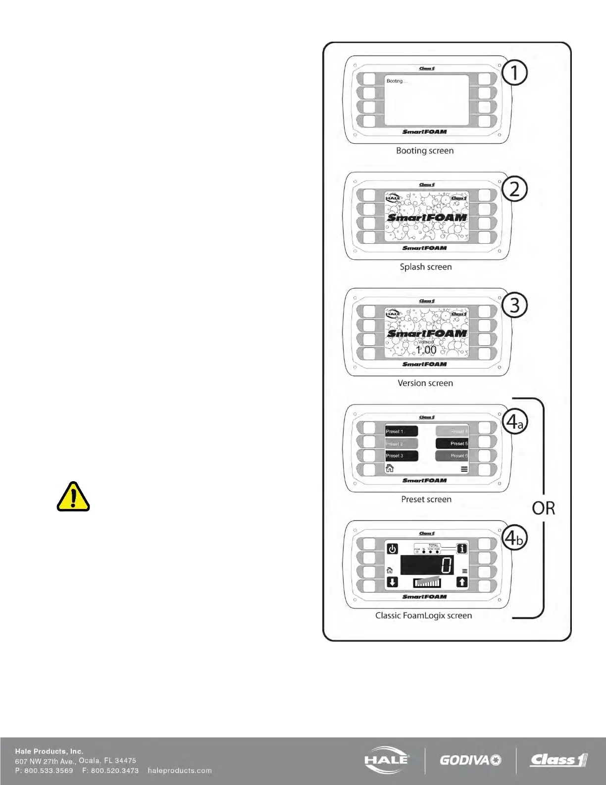
❑ SmartFOAM booting screen is shown for three
seconds.
❑ SmartFOAM splash screen is shown for three
seconds.
❑ SmartFOAM version screen is shown for two
seconds.
❑ SmartFOAM preset screen is shown (default)
OR
SmartFOAM classic FoamLogix screen is
shown.
(The screen shown depends on the “display for-
mat” chosen in the user menu).
(See Figure 57).
If a default display does not appear, refer to the TROU-
BLESHOOTING section for possible WARM-UP/ SYS-
TEM CHECKING causes and solutions.
INITIAL SYSTEM CHECK
After initial system power-up the low tank level sensor
operation, foam pump operation, and flow sensor cali-
bration must be checked per the following:
CAUTION!
WATER IS USED AT THE SYSTEM INSTALLER FA-
CILITY TO VERIFY LOW TANK LEVEL SENSOR SYS-
TEM READY OPERATION AND FOAM PUMP OPERA-
TION AS THE END USER SPECIFIED FOAM
CONCENTRATES MAY NOT BE READILY AVAILA-
BLE.
DO NOT PUMP WATER WITH THE HALE FOAM-
LOGIX FOAM PUMP FOR MORE THAN ONE (1) MI-
NUTE. DO NOT ATTEMPT TO CALIBRATE FOAM
PUMP FEEDBACK SENSOR WITH OTHER THAN
END USER SPECIFIED FOAM CONCENTRATE.
MAKE SURE THE BYPASS VALVE IS IN THE BY-
PASS POSITION WHEN PUMPING WATER WITH THE
FOAM PUMP.
Figure 57: Controller Unit Initialization