Page 77
USER CALIBRATION
The complete Hale SmartFOAM Systems foam pump
and motor assembly, controller unit and flow sensor is
tested at the factory before shipping to the installer.
If the
Hale SmartFOAM system is properly installed, further
calibration IS NOT necessary until delivery to
customer.
The system permits easy checking of component calibra-
tion to assure accurate operation. The calibration pro-
cess verifies component calibration and allows adjust-
ments to the flow sensor and feedback sensor display
readings to allow for
variations in apparatus piping con-
figurations and end user selected foam concentrate.
Default values for simulated flow and foam concentrate
injection rate may be set to end user specifications while
in the calibration mode.
The SmartFOAM controller allows up to 6 user preset
foam injection rates. Each preset allows for custom text
and color for easy identification.
Note: The Hale SmartFOAM system is calibrated at the
factory to U.S. measurement (GPM, PSI,
GALLONS,
etc.) units. The system may be set
to Metric units (see
heading “English to Metric Units”). However, the same
unit of measurement must be used throughout the cali-
bration process to ensure proper proportioning by the
system.
Recalibration of the system may be required ONLY
after
major repairs or component changes are made to the
Hale SmartFOAM foam system. Different viscosity foam
concentrates may also require recalibration.
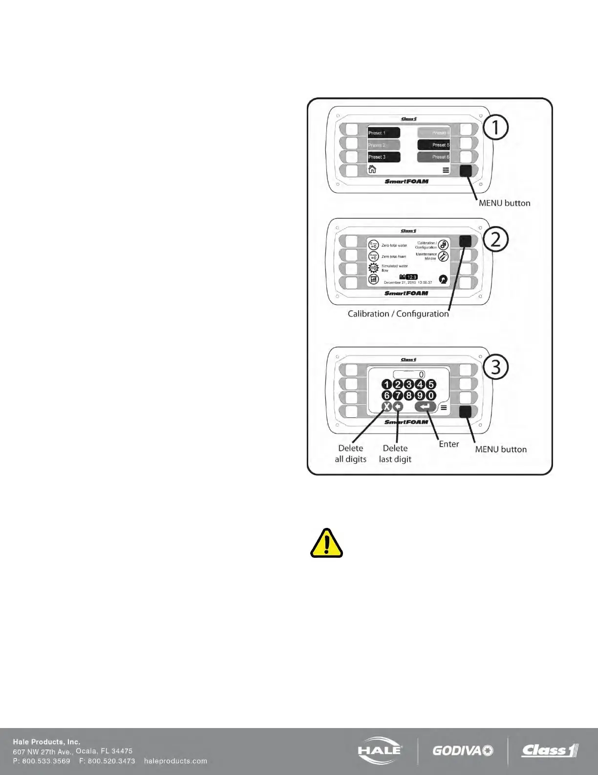
ENTERING PASSWORDS
System calibration and configuration is accomplished by
accessing screens which are protected via passwords.
To enter a password:
1. Press the MENU button to go to the system
menu.
2. Press the Calibration/Configuration button on the
system menu screen.
3. Use the touch screen keypad to enter the de-
sired password.
a. Press the “Enter” touch screen button to
submit the password.
b. Press the “Delete last digit” touch screen
button to erase the last digit entered.
c. Press the “Delete all digits” touch screen
button to erase all of the digits entered.
When a valid password is submitted the screen will auto-
matically change to the screen dictated by the password
value.
If an invalid password is submitted the display will show an “X”
across the password window for two seconds.
F
igure 61: Entering Passwords
WATER FLOW CALIBRATION
IMPORTANT!
AN ACCURATE FLOW MEASURING DEVICE MUST BE
USED TO MEASURE THE WATER FLOW WHEN CALIBRAT-
ING THE FLOW SENSOR. USE A SUITABLE SIZE, SMOOTH
BORE, NOZZLE AND AN ACCURATE AND CALIBRATED PI-
TOT GAUGE INSTRUMENT. HANDHELD PITOT GAUGES
ARE USUALLY NOT VERY ACCURATE.
MAKE SURE THE SYSTEM IS CALIBRATED WITH AN AC-
CURATE FLOW MEASURING DEVICE.
Enter the password “6679”. The controller will show the water
flow calibration screen.
Water flow calibration requires setting two calibration points: one
at a high rate of flow and the second at a lower rate of flow.