Configure sensor parameters in HBK ADVANTAGE
Configure sensor parameters in HBK ADVANTAGE
To configure the sensor parameters of a selected channel, click Properties in the toolbar. Click the
Sensor tab.
Every sensor has specific setup parameters depending on the type of sensor. The type of sensor (as defined
in the "Configure channel parameters in HBK ADVANTAGE" on the previous page) is shown at the top of the
panel.
When the sensor is a bridge
Sensor = Quarter bridge, Half bridge or Full bridge
Wiring: The connector wiring for the selected sensor. Select between the following:
l
Quarter bridge: 3-wire or 4-wire
l
Half bridge: 4-wire or 5-wire
l
Full bridge: 4-wire or 6-wire
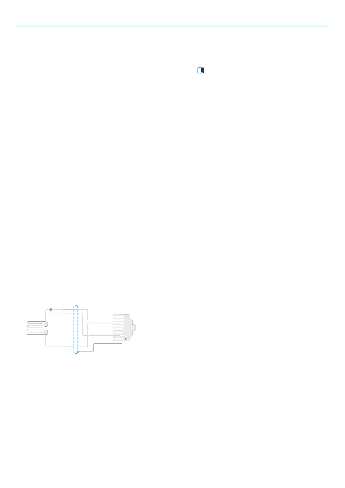
Under Connector pinning, a diagram of the sensor's pinning is shown for reference.
Excitation voltage: The constant supply voltage needed to power the sensor. Select one of the following
DC/AC values (where AC is carrier frequency) in volt (V): 1.0, 2.5, 5.0 or 10.0.
Excitation mode: Define the type of excitation, either DC or Carrier frequency (AC).
Resistance: Resistance varies with each sensor. For quarter-bridge sensors, select one of the following Ohm
(Ω) values: 120, 350 or 1000.
Connector pinning
Use the diagram to confirm that the sensor pinning matches the wiring of the sensor type.
Figure 3-1 Example of a 3-wire quarter bridge strain gauge as shown in HBK ADVANTAGE
Characteristics
For each channel, individual sensor scaling can be defined and applied. The scaling type will determine what
other parameters need to be defined.
Go to "Sensor characteristics" on page44 for information on these parameters.
- 41 -