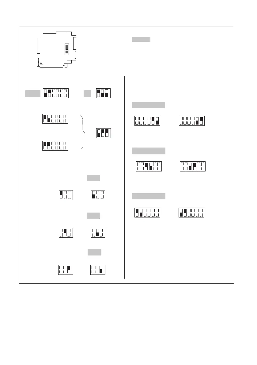
MP60, MP60DP
AMPLIFIER SETTINGS WITH DIP SWITCHES
14
S11
S5
S6
S12
S4
123
ON
S6
Line termination resistor 120 Ω
3)
Frequency
input F1
123
ON
123
ON
Input signal unbalanced/balanced
2)
Factory setting:
Frequency
input F2
Reference zero
123456
ON
Frequency input F1
123456
ON
Frequency input F2
123456
ON
Reference zero
S5
Analog output
1)
123456
ON
S11
123
ON
S4
±10V
±20mA
123456
ON
123
ON
123456
ON
4…20 mA
V
mA
S4
S11
S11
ON
123
S6
123
ON
123 123
ON
123456
ON
balanced unbalanced
123456
ON
123456
ON
balanced unbalanced
balanced unbalanced
OffOn
OffOn
OffOn
1)
View/check in the display under ANALOG
OUTPUT group, parameter "Mode Vo";
see page 33
2)
Depending on transducer
3)
Activate (F1, F2 reference zero to ON) with
balanced output signals and long
measurement leads (u100 m).
Fig. 4.3 Amplifier adjustment