MP60, MP60DP
CONNECTION
18
6 CONNECTION
WARNING
Comply with the safety instructions before starting up the device.
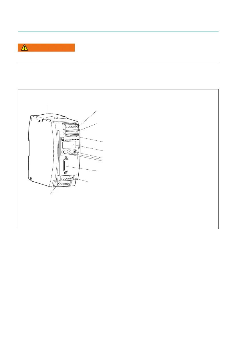
6.1 Function overview
Plug terminal 1: Power supply and CAN bus,
synchronization
Transducer connection (15-pin sub-D connector)
Plug terminal 3: Galvanically isolated
1)
control inputs
(24 V level), analog output
Pressure-sensitive control keys
2-row LCD display
Plug terminal 2: (same assignment as plug terminal 1)
CAN adapter for PC/laptop connection, parameterization
via CAN bus
Plug terminal 4:
Galvanically isolated control outputs (24 V level), external supply of control inputs
LED
Local connection of CAN bus, supply voltage and synchronization between modules
1)
Galvanic isolation referred to measuring amplifier (measuring circuit), and control inputs and outputs
have a common reference potential
MP60