19
MP60, MP60DP
CONNECTION
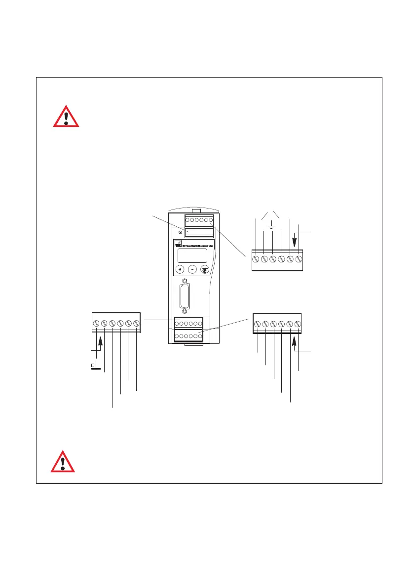
6.2 Supply voltage and control inputs/outputs and CAN interface
There are four removable plug terminals available for connection.
0 V
SYN
Analog‐OUT
±10 V
±20 mA
4...20 mA
IN1
IN2
IN3
IN4
0 V
24 V
OUT1
OUT2
OUT3
OUT4
Plug terminal 3
Plug terminal 4
LH
Plug terminal 1
IN = digital input, OUT = digital output
For more detailed information on inputs and outputs, see section 8, page 43.
ATTENTION:
If the mains power to the MP60 module fails, all control outputs will be set to 0 V.
24 V
Labeling
Labeling
Labeling
Plug terminal 2
Connecting the power supply
WARNING
The MP60 module must be connected to an external voltage of 18-30 V
DC
(24 V
nom
).
- Twist the ends of the power supply cable and fit them with wire end ferrules.
- Screw the wire ends to screw terminal 1.
- Insert the plug terminal into the top socket.
- Switch on the power supply.
Power supply
MP60
CAN
Fig. 6.1 Plug terminal assignment