MP60, MP60DP
AMPLIFIER SETTINGS WITH DIP SWITCHES
12
4 AMPLIFIER SETTINGS WITH DIP SWITCHES
Important
The DIP switches must be set/adjusted before mounting the PME.
Various settings are made using DIP switches. These are the settings for:
line termination resistor, frequency input signals, input circuit (unbalanced, balanced),
analog output, synchronization, bus termination resistor, edge steepness
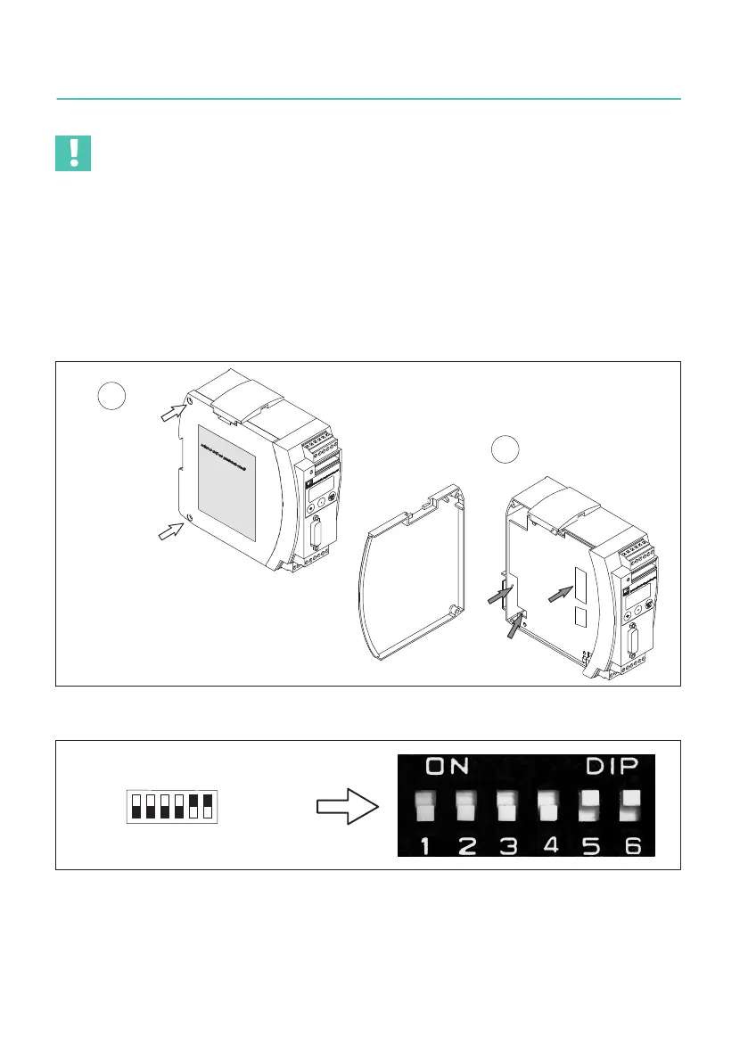
Set the DIP switches as shown in Fig. 4.1.
S5
S4
S10
S11
S12
Unscrew cover
1
2
S6
Fig. 4.1 Opening housing, position of DIP switches
12 34 56
Example:
means
ON
Fig. 4.2 Switch convention