23
MP60, MP60DP
CONNECTION
Important
The MP60 can indicate transducer errors generated by the torque sensor. But to do this,
the error signal from the torque sensor must be connected across pin 7 of the transducer
plugs (15-pin sub-D plugs).
The "transducer error" function in the MP60 must also be activated.
6.4 Synchronization
Synchronization of the modules ensures simultaneous measured value acquisition and
processing.
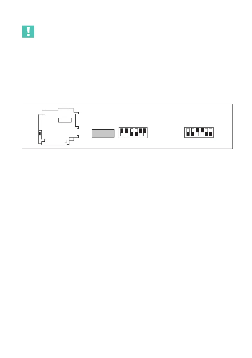
123456
ON
S10
123456
ON
Master
Slave
S10
S10
Fig. 6.5 Master/slave setting
When synchronizing multiple modules, one device must be declared the master. The
other devices must be set as slaves.
Even if modules work without a CAN bus, the ribbon cable should always be used for
synchronization between them.
6.5 CAN interface
The CAN bus is connected via plug terminal 1. A maximum of 32 CAN nodes may be
connected in one bus segment.
The CAN bus requires a 120 Ω. A termination resistor is integrated into the MP60 module,
and is activated by toggle-switch S14 (see page 15).