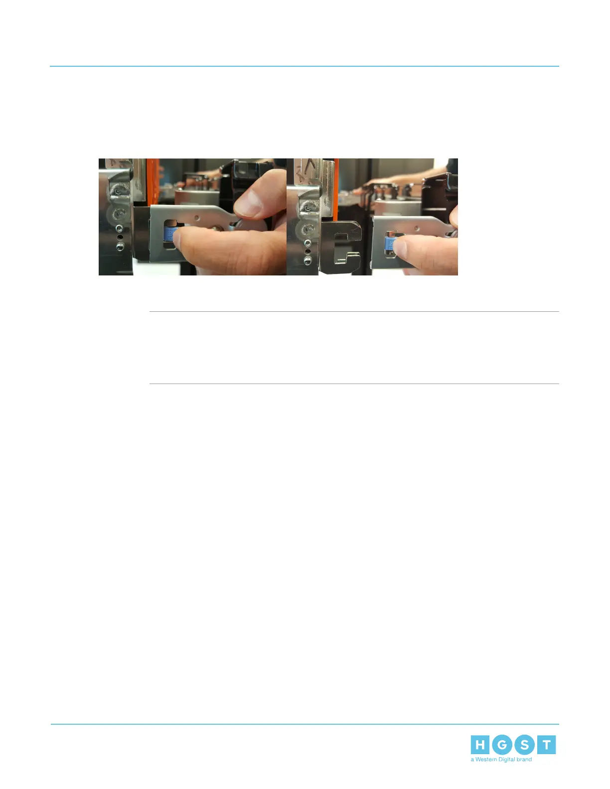
6. Unlatch all of the connectors that attach the CMA to the enclosure and the rail by locating the latch release
button and pressing it from either side of the latch. There are three total connections that need to be
removed, one at the elbow and two at the opposite end.
Figure 65: Unlatching a CMA Connector
7. Follow the previous step for the second CMA.
8. Install the lower CMA.
a)
Note: The CMA has two arms that are labeled upper and a lower. These arms are connected
to the rails and the enclosure's chassis by four connectors. The first step in installing one of
the arms for the CMA is to first determine what orientation the arm needs to be in. The lower
arm should have the elbow on the right side, the upper arm should have the elbow on the left
side.
Orient the CMA so that the elbow is on the left hand side.
74
4 Part Replacement
User Guide 4.7 CMA Replacement

 Loading...