92
Electrical Wiring
5.2 Electrical Data
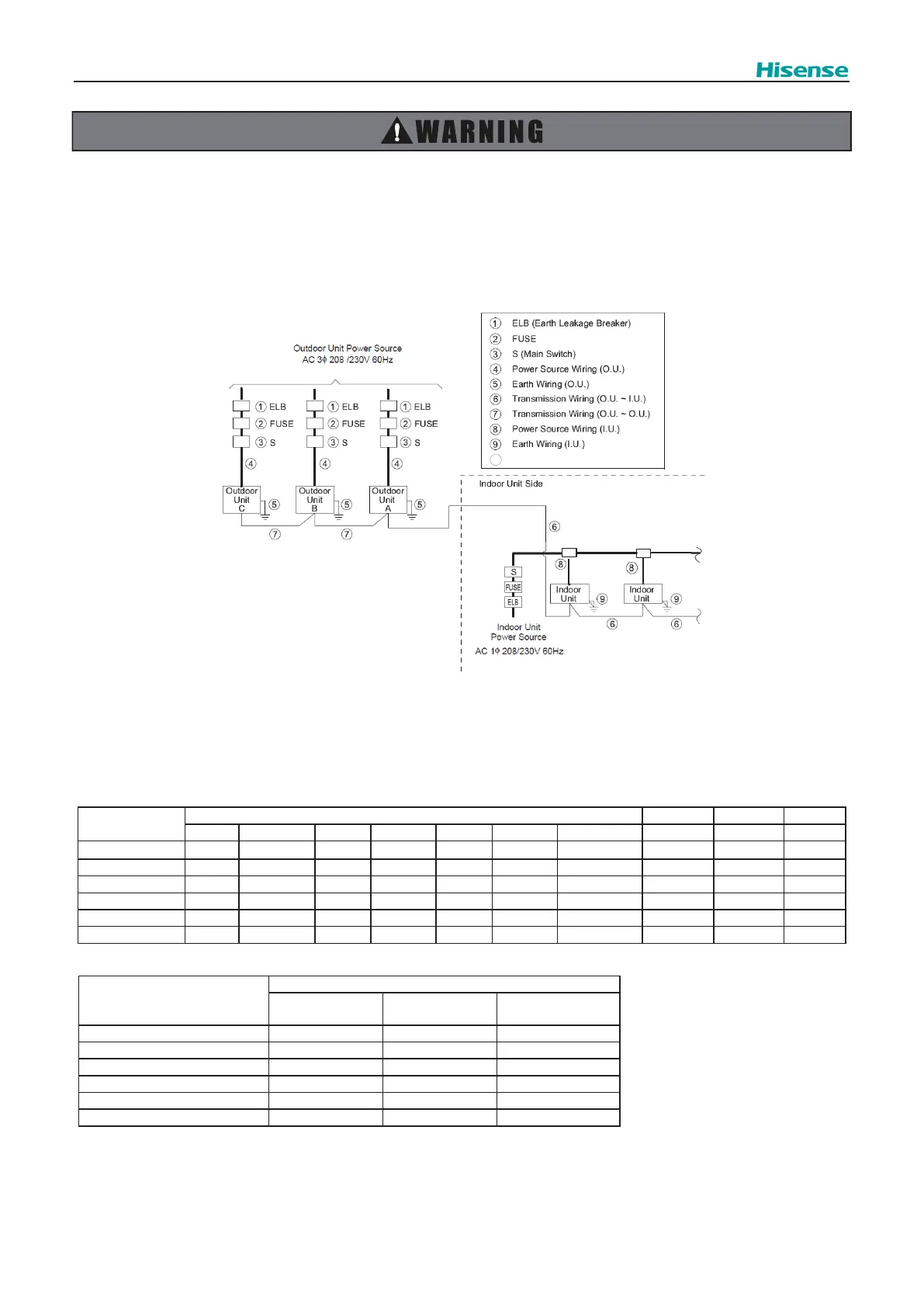
The ELB (earth leakage breaker), FUSE and S (main switch) must be installed to the each power source of outdoor unit. If
not, it may cause an electrical shock or a re.
Perform the electrical work according to the regulations of each region and this manual.
NOTE: Supply the power source of outdoor units and indoor units respectively.
(1) Power Supply Wiring
Supply the power sources to the each outdoor unit respectively. Power source wiring is fundamentally according to this
method.
(2) Electrical Characteristics
Note the following when selecting wiring:
● Use the charts below to select appropriate sized breakers / fuses / overcurrent protection switches and wiring in
accordance with local codes.
● Ensure communication cable is a minimum of AWG18 (0.82mm²), 2-Conductor, Stranded Copper.
Table 5.1 Minimum Wire Sizes for Power Source on Field
Model
Outdoor Unit Inverter 1 Inverter 2 Fan Motor
Hz (Hz) Voltage (V) Max. (V) Min. (V) MCA (A) MOP (A) Max. Fuse (A) MOC (A) MOC (A) FLA (A)
AVWT-72FFFH 60 208/230 253 188 34.3 45 45 25.2 - 2.8
AVWT-96FFFH 60 208/230 253 188 41.2 50 50 30.7 - 2.8
AVWT-120FFFH 60 208/230 253 188 49.3 60 60 37 - 1.5×2
AVWT-144FFFH 60 208/230 253 188 60.1 80 80 24.2 24.2 2.8×2
AVWT-168FFFH 60 208/230 253 188 62.3 80 80 25.2 25.2 2.8×2
AVWT-192FFFH 60 208/230 253 188 78.1 100 100 32.2 32.2 2.8×2
Model
Wiring Size
Power Supply
Wiring (AWG)
Ground Wiring
(AWG)
Communication
Cable (AWG)
AVWT-72FFFH 8 8 18
AVWT-96FFFH 8 8 18
AVWT-120FFFH 6 6 18
AVWT-144FFFH 4 4 18
AVWT-168FFFH 4 4 18
AVWT-192FFFH 2 2 18
MCA: Minimum Circuit Ampacity (A)
MOP: Maximum Overcurrent Protective Device (A)
MOC: Maximum Operating Current (A)
FLA: Fan Motor Running Ampacity (A)
Distribution Box
10
 Loading...