3
Introduction
1.2 Application Case
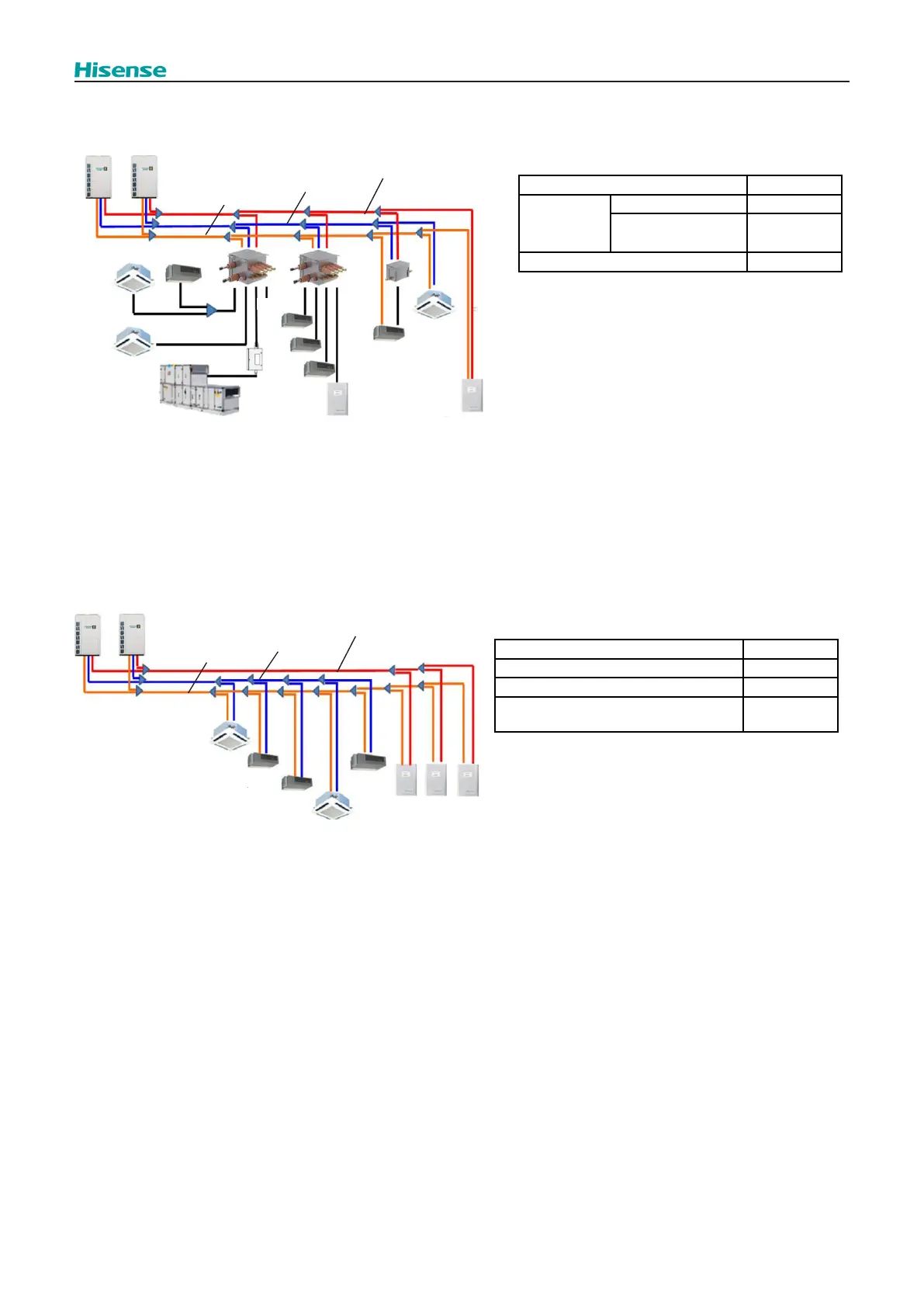
Application Case 1: Three Pipes Heat Recovery System with Switch Box
.
IU
Simultaneous
Cooling/Heating
WM
Simultaneous
WM
Heating Only
IU
Cooling
Only
AHU
Cooling/Heating
High /Low pressure gas pipe
Low pressure gas pipe
Liquid pipe
Capacity Ratio
Total Capacity Ratio 50%~150%
Indoor Unit
Total 50%~150%
Without SW
Box(CoolingOnly)
0%~50%
Water Module 0%~60%
NOTE
:
(1) The function setting of “H4” must be set to 0 on
the outdoor unit PCB (default setting).
(2) The function setting of “n3” must be set to correct
value equal to the quantity of water module
connected on the outdoor unit PCB.
(3) WM with Simultaneous Cooling/heating must
occupy one branch of SW Box exclusively.
Application Case 2: Three Pipes Heat Recovery System without Switch Box
IU
Cooling
Only
Cooling
Only
Cooling
Only
IU
Cooling
Only
Cooling
Only
WM Heating Only
High /Low pressure gas pipe
Low pressure gas pipe
Liquid pipe
Total Capacity Ratio 100%~200%
Indoor Unit (Cooling Only) 50%~100%
Water Module (Heating Only) 50%~100%
Capacity Ratio of Indoor Unit to Water
Module
80%~130%
NOTE
:
(1) The function setting of “H4” must be set to 0 on the
outdoor unit PCB (default setting).
(2) The function setting of “n3” must be set to correct
value equal to the quantity of water module connected
on the outdoor unit PCB.
 Loading...