157
Troubleshooting
Alarm
Code
31
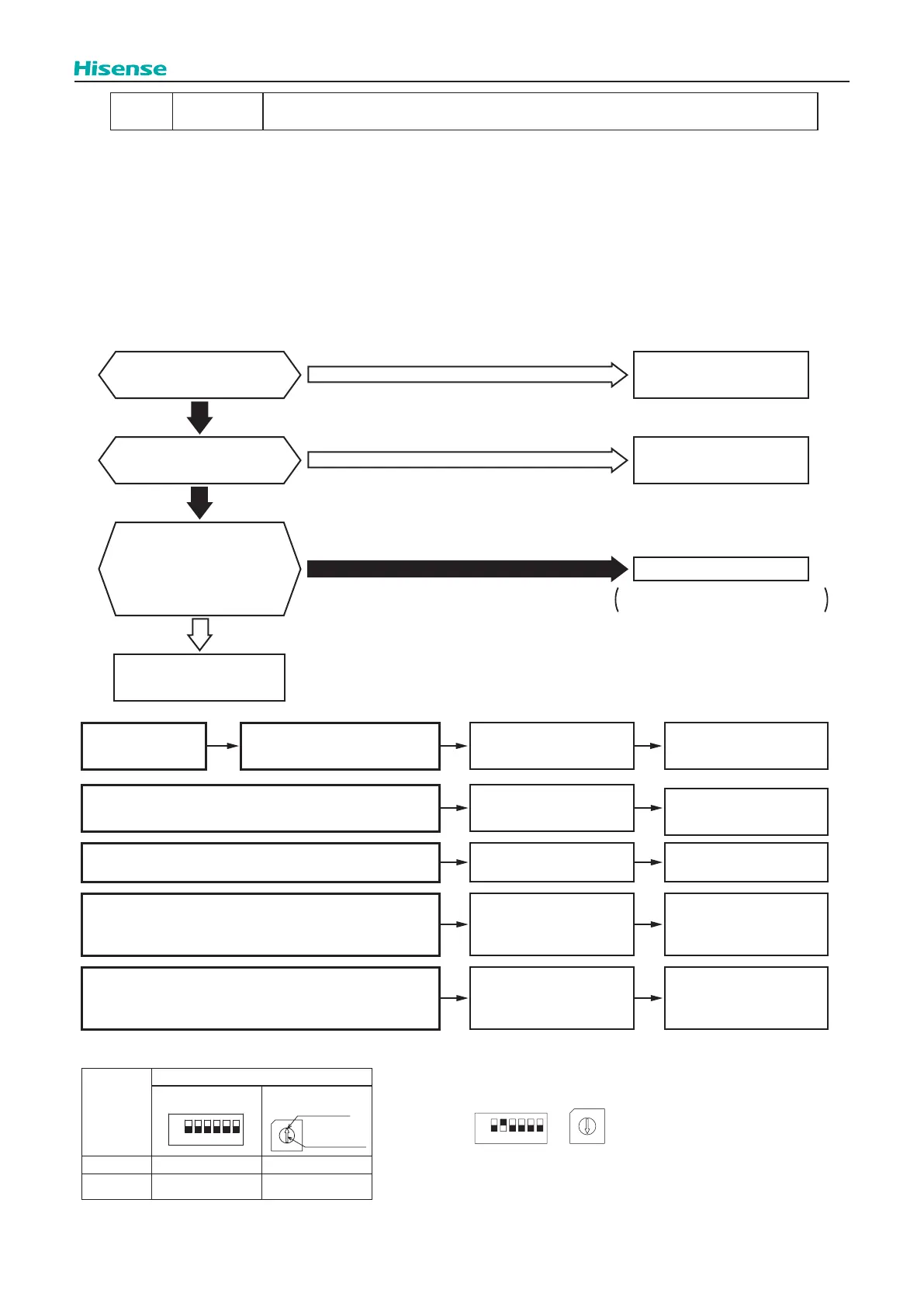
Incorrect Capacity Setting of Indoor Unit and Outdoor Unit
● The RUN indicator (Red) is ashing
● The indoor unit number, the alarm code, the unit model code and the connected number of indoor units are displayed on
LCD. Meanwhile, the indoor unit number and the alarm code are displayed on the 7-segment of outdoor unit PCB.
★
This alarm code is indicated when the capacity setting dip switch, DSW2 on the outdoor unit PCB, is not set (all the
settings from #1 to #6 are OFF) or set incorrectly.
★
This alarm code is indicated when the total indoor unit capacity is smaller than 50% or greater than 150% of the combined
outdoor unit capacity. This alarm code also can be triggered when Water Module capacity is greater than 100% of the
combined outdoor unit capacity or improper function setting of “H4” on the outdoor unit PCB for Water Module application.
Are #1-#6 of DSW2 on
O.U. PCB set incorrectly?
Are the setting of
DSW1 and RSW1 on
O.U. PCB and the setting
of DSW5 and RSW2 on
I.U. PCB totally same in
a refrigerant cycle?
Total indoor unit capacity
is wrong.
Set the capacity for
O.U. PCB.
No
Yes
Yes
Yes
Are #1-#4 of DSW3 on
I.U. PCB set incorrectly?
Set the capacity for
I.U. PCB.
No
Set them correctly.
No
Outdoor Unit PCB: DSW1, RSW1
Indoor Unit PCB: DSW5, RSW2
Cause Check Item
Action
(Turn OFF Main Switch)
Phenomenon
Check combination of
indoor units and capacity
setting on I.U. PCB.
Correctly set dip switch,
DSW3.
Incorrect Capacity Setting of Indoor Unit
Check outdoor unit
model by calculating
total indoor units
capacity.
Ensure that total
indoor unit capacity is
from 50% to 130%.
Total Indoor Unit Capacity Connected to the
Outdoor Unit is Beyond Permissible Range
Check refrigeration cycle
setting on O.U. PCB
and I.U. PCB.
Set them correctly.
Refrigeration Cycle Setting of Outdoor Unit
and Indoor Unit is Different
Check capacity setting
on O.U. PCB.
Correctly set dip switch,
DSW2.
Incorrect Capacity Setting of Outdoor Unit
DSW and RSW setting before shipment is 0.
Maximum in setting refrigerant cycle No. is 63.
Setting Switch
10 digit 1 digit
Outdoor Unit DSW1 RSW1
Indoor Unit
(H-NET II)
DSW5 RSW2
1234
ON
5 6
OFF
0
7
9
5
8
6
4
3
1
2
Setting Position
Set by inserting
slotted screwdriver
into the groove.
Example of Setting Refrigerant Cycle No. 25
0
7
9
5
8
6
4
3
1
2
1234
ON
5 6
OFF
Turn ON No. 2 pin. Set Dial No.5.
O.U. PCB: Outdoor Unit PCB
I.U. PCB: Indoor Unit PCB
Refrigerant Cycle No. Setting
 Loading...