93
Electrical Wiring
Install a multi-pole main switch with a space of 1/8in.(3mm) or more between each phase.
NOTES:
(1) When the power supply wiring is longer, select the minimum wiring size of which the voltage drop is within 2%.
(2) Power supply voltage should be satised with the followings:
supply voltage: within +10% of rated voltage
starting voltage: within -15% of rated voltage
operating voltage: within ±10% of rated voltage
imbalance between phases: within 3%
(3) Do not connect the earth wire to the gas pipe, water pipe, lightening conductor.
Gas pipe: an explosion and ignition may occur when gas leaks.
Water pipe: there is no eect of earth wire when a hard vinyl pipe is used.
Lightening conductor: the earth electric potential abnormally increases when a lightening conductor is used.
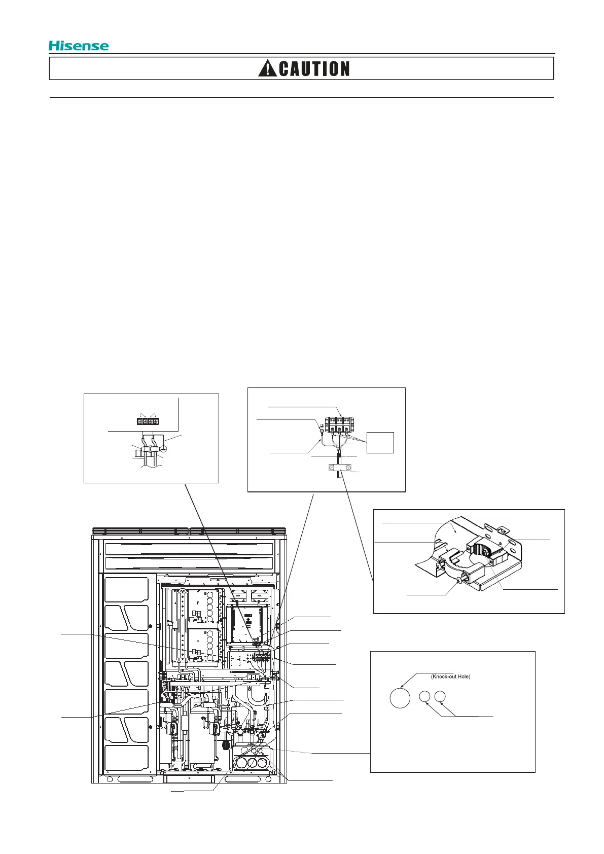
5.3 Electrical Wiring Connection
Connect the electrical wirings according to the following gure.
(1) Fix the cord band base onto the mounting plate with the short screw, the cord band base and short screw are in the
fastener pouch.
(2) Wrap power wiring once around the big magnet ring in electrical accessory pouch, lead power wiring and earth wiring
through the hole on the mounting plate and mount the cord band with the long screw to secure power wiring and earth
wring; then connect power lines to Terminal on TB1, and earth wire connect to the terminal in the electrical control box.
(3) Wrap transmission wiring between indoor and outdoor units twice around the small magnet ring in electrical accessory
pouch, then connect it to Terminal 1 and 2 of TB2 on PCB1. As for transmission wiring between outdoor units of the
same refrigerant system, please connect to Terminal 3 and 4 of TB2 on PCB1.
(4) Tighten screws on the terminal block, and secure power wiring and transmission wiring with cord clamp
.
Earth Wire
for O.U.
to O.U.
TB2
PCB1
Shielded Twist
Pair Cable from
Indoor Unit
to Outdoor Unit
Shielded Twist
Pair Cable for
between Outdoors
Transmission
Cord Clamp
for I.U.
to O.U.
1
2
3
4
L2 L3L1
Ground
Wiring
Terminal Block for
Power Supply Wiring
(TB1)
Ground Wiring
Terminal (Connect
securely cable.)
Attach
insulation
sleeve.
Power Supply WiringΦ1-23/32(Φ43.7)
Operating Wiring
Φ55/64(Φ22)
(Knock-out Hole)
NOTE: seal hermetically the entry of the conduit by using putty
or etc. to avoid the ingress of water.
Mounting Plate
Cord Band
Long Screw
Cord Band Base
Short Screw
Cord Band
NOTE: refer to the above picture for the installation of cord band and cord band
base. all parts above are in the fastener pouch
Terminal Board for
Transmission Wiring
Cord Clamp
Terminal Board
For Power Supply
(for Transmission Wiring)
Transmission Wiring
(install small magnet ring)
Cord Clamp
Power Supply Wiring
(install big magnet ring)
(for Power Wiring)
Cord Clamp
Connection Hole of
Transmission Wiring
Connection Hole of
Power Supply Wiring
Earth Wiring
Cord Band
 Loading...