253
Servicing
TURN OFF all the power switches.
Do not touch any electrical components while LED3 (Red) on Inverter PCB is ON.
Otherwise, an electric shock will occur.
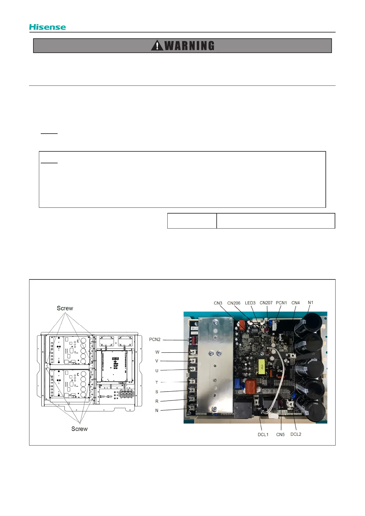
2.17.2 Removing Inverter PCB
(1) Disconnect all the wirings connected to the CN3, CN4, CN5, CN206, CN207, PCN1, PCN2.
(2) Disconnect the wirings for the Inverter PCB(U,V,W,T,S,R,N,N1,DCL1,DCL2).
(3) After removing four (4) screws, remove the inverter PCB.
NOTE:
Do not touch any electrical components while LED3 (red) of inverter PCB is ON. Otherwise, it may lead to an electric
shock.
NOTE:
1. When reassembling the electrical components, match the terminal Nos. with the mark band Nos. . If they are
incorrectly connected, malfunction may occur or the electrical components may be damaged.
2. When closing the outdoor unit PCB xing plate for reassembly, protect the cables from catching on the plate edges
or electrical components.
Tool Phillips Screwdriver
 Loading...