103
Test Run
(1) Conrm that eld-supplied electrical components (main switch fuse, fuse-free breaker, earth leakage breakers, wires,
conduit connectors and wire terminals) have been properly selected according to the electrical data given in the
Technical and Installation Hand book of the unit and ensure that the components comply with national and local codes.
(2) Use shielded wires (>18AWG(0.75mm²)) for eld wiring to protect from electric noise obstacle (total length of shielded
wire shall be less than 3230.8ft.(1000m), and size of shielded wire shall comply with local codes).
(3) Check to ensure that the terminal for power source wiring (the voltage of terminals “L1” to “L1” and of shielded wire
shall comply with local codes.). If not, some components will be damaged.
7.2 Test Run
(1) Check to ensure that the stop valves of the outdoor unit are fully opened and then start the system.
(In case of the combination module, check that the stop valves of all the connected outdoor units are fully opened.)
NOTE: Low pressure gas is used for heat recovery system only.
(2) Perform the test run of indoor units one by one sequentially and then check corresponding refrigerant piping system and
electrical wiring system. (If multiple indoor units operate simultaneously, the system can not be checked for the system
accordance.)
(3) Perform the test run according to the following procedure. Ensure that the test run is carried out without any problems.
NOTE: In case of 2-remote control switch (main and sub), rstly perform the test run of the main remote control switch.
(a) Set the “TEST RUN” mode by pressing the “MODE” and “CHECK” switch of controller simultaneously for at least 3
seconds.
●Regarding other optional remote control switch (wireless remote control or half-size remote control), follow
“Installation & Maintenance Manual” attached to each optional remote control switch and perform the test run.
●In case that the multiple indoor units operate simultaneously controlled by one remote control switch, check the
connected number of indoor unit is indicated on LCD.
In case that the indicated number is not correct, the auto-address function is not performed correctly due to incorrect
wiring, the electric noise or etc. Turn OFF the power supply and correct the wiring after checking the following points; (Do
not repeat turning ON and OFF within 10 seconds.)
* Power Supply for Indoor Unit is Not Turned ON or Incorrect Wiring.
* Incorrect Connection of Connecting Cable between Indoor Units or Incorrect Connection of Controller Cable
* Incorrect Setting of Rotary Switch and DIP Switch (The Setting is overlapped.) on the Indoor Units PCB.
(b) Set the operation mode by pressing “MODE” switch.
(c) Press “RUN/STOP” switch.
→The operation lamp will be turned ON before the test run starts.
2-hour OFF Timer will be set automatically, and “OFF Timer” and “2HR” will be indicated on LCD. Although the air
ow initial setting is “HI”, the setting can be changed.
●Check the operation range according to page I.
* Do not touch any of the parts by hand at the discharge side, since the compressor chamber and the pipes at the
discharge side are heated to above194°F(90°C).
* DO NOT PUSH THE BUTTON OF THE MAGNETIC SWITCH(ES). It will cause a serious accident.
●Do not touch any electrical components for at least 10 minutes after turning OFF the main switch.
●Check that the refrigerant piping setting and electrical wiring setting are for the same system, by operating the indoor
unit one by one.
(d) Depress “AUTO LOUVER” switch and check that the louver is activated normally without abnormal sound. Depress “AUTO
LOUVER” again so that the louver will stop. If there is abnormal sound, remove the panel and adjust the tting condition
of connection parts in the panel corner cover. Ensure that the panel is mounted correctly to the unit body, otherwise the
panel may be deformed.
(e) The temperature control will be invalid though the protection device will be activated during the test run. If alarm occurs,
nd out the cause of abnormality according to Service Handbook. And again perform the test run after solving the
problems.
(f) According to the label “Checking of Outdoor Unit by 7-segment Display on PCB1” attached to the rear side of the front
cover of the outdoor unit, inspect temperature, pressure, operation frequency, and connected indoor unit numbers by the
7-segment displays.
(g) To end the test run, wait for 2 hours or push “RUN/STOP” switch again.
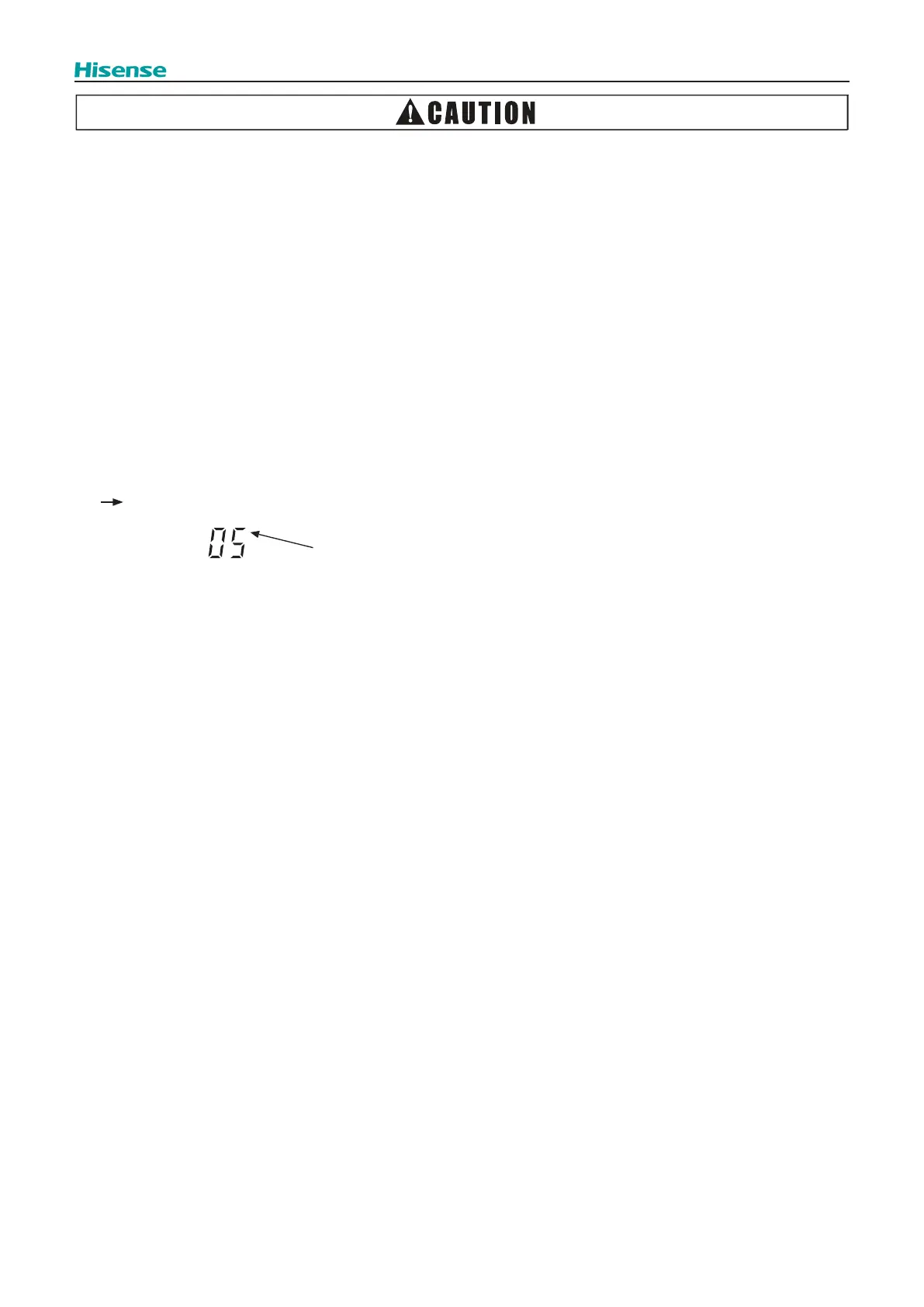
"TEST RUN" is displayed on the LCD.
The total number of the indoor units connected is indicated on the LCD.
unit
Example when 5 indoor units are connected.
 Loading...