99
Electrical Wiring
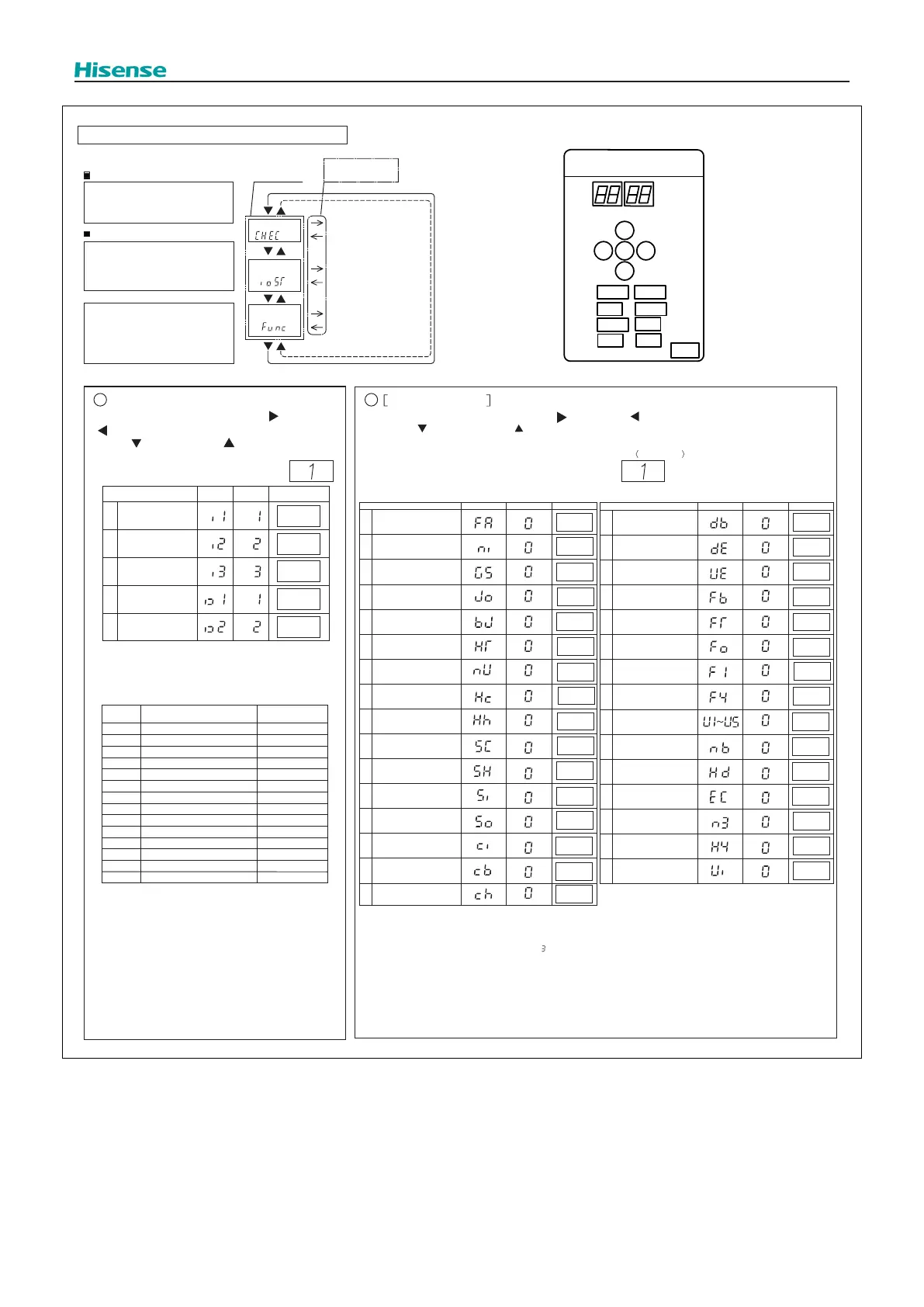
● Function Setting
2
1
2
3
4
5
SEG1SEG2
1
“
”
(Setting
before
shipment)
Before shipping, the input/output function settings are
specified to each input/output terminal according to above table.
External Input/Output and Function Setting
Start of Setting
Turn ON DSW4-No.4.
Press PSW1 for at least 3 seconds.
“Menu
Mode”
will be indicated.
End of Setting
Press PSW1 for at least 3 seconds.
The display indication become to
normal indication.
Turn OFF DSW4-No.4.
NOTE:
Release “Menu Mode” after the
setting is completed.
Otherwise, the air conditioner
may not operate properly.
Menu Mode
Press PSW1 once.
Check Mode
External Input an d
Output
Function Setting
For more details,
refer to “Checking of
Outdoor Unit by PCB”
in the Service Manual.
For the setting mode,
refer to ① below.
For the function setting,
refer to ② below.
By pressing the push-switches PSW3 ( )and PSW5
( ), the functio
n
No. can be selected.
PSW4 ( ): forward, PSW2 ( ): backward
Fill out the selected function setting No. in
the box o
f the table as shown on the right.
<Example>
Item
SET
Input Setting 1
Input Setting 2
Input Setting 3
CN17[1-2 pin]
CN17[2-3 pin]
CN18[1-2 pin]
Output Setting 1
CN16[1-2 pin
Output Setting 2
CN16[1-3 pin]
The same input/output function setting can not be set to
different input/output terminals.
If set, a setting of larger function number is invalid.
Function Setting
By pressing the push-switches PSW3 ( ) and PSW5 ( ), the setting can be changed.
PSW4 ( ): forward, PSW2 ( ): backward
Refer to the service handbook for more details.
Fill out the selected function setting No. in the
space of the table as shown.
Example
”
[External Input and Output Setting]
Setting External Input/Output Functions
“
“
”
SEG2 SEG1
PSW3
PSW2
PSW1
PSW4
PSW5
DSW6
DSW5
DSW4
DSW2
DSW3
DSW7
DSW1
DSW8
DSW10
Arrangement of DIP
Switch Setting
Note:
(1)The function setting of "n3" must be set to correct value according to the quantity of water module connected,
otherwise, ALARM 37 may be triggered. (For example, in case of the quantity of water module in a system is
three, then the value of "n3" should be set to " ". )
(2)The function setting of "H4" must be set to correct value according to the type of water module connected:
H4=0 (default) : water module should be used in a three -pipe heat recovery system.
H4=2: water module should be used in a two -pipe heat pump system.
(2)The function setting of "Ui" can be set according to application requirement:
Ui=0 (default) : performance balance between indoor unit and water module.
Ui=1: indoor unit has priority on performance.
SEG2 SEG1 SET
1
Fan Intermittent Operation
during Heating Thermo-OFF
2 Night-Shift
3
Cancellation of Outdoor
Ambient Temperature Limit
4
Defrost at Cold Area
(Change of Defrost Condition)
5
SLo (Fan Speed)
Defrost Setting
6 Cancellation of Hot Start
7 Priority Capacity Mode
8
Frequency Control
(Control Target Value for
Cooling Compressor)
9
Frequency Control
(Control Target Value for
Heating)
10
Indoor Expansion Valve
(Control Target Value for
Cooling)
11
Indoor Expansion Valve
(Control Target Value for
Heating)
12
Indoor Expansion Valve
(Opening during Heating
Operation Stoppage)
13
Indoor Expansion Valve
Opening during Heating
Thermo-OFF
14
Indoor Expansion Valve
Initial Opening during
Heating Thermo-ON
15
Indoor Expansion Valve
Initial Opening for Cooling
16
Outdoor Expansion Valve
Initial Opening for Heating
Item
SEG2 SEG1 SET
17
Sound Reduced Function
18
Demand Function Setting
19
Wave Function Setting
20
Protection of Decrease in
Outlet Temperature for Cooling
21 Reserved
22
Adjustment of Fan Rotation
(for multiple installation)
23
Min. Indoor Exp-Valve
Opening Setting at Heating
Functions SW-OFF
24 Snow Model Setting
25 Indoor VIP Function
26 Automatic Night-Shift
27
Height Difference
Setting
28
Economic Fuction
Setting
29
Quantity of Water
Module Connected
30 Type of Water Module
31
Performance Balance
between Indoor Unit and
Water Module
Item
10
1
2
4
5
6
7
8
9
11
12
13
-
-
-
-
-
-
-
-
-
Function
Input
No.
Output
Fixing Heating Operation Mode
Demand Stoppage
Forced Stoppage
Demand Current Control 40%
Demand Current Control 60%
Demand Current Control 70%
Demand Current Control 80%
Demand Current Control 100%
Low Noise Setting 1
Low Noise Setting 2
Low Noise Setting 3
Fixing Cooling Operation Mode
Compressor ON Signal
Outdoor Fan Motor Start/Stop
Frost Signal
3
Warning Signal
0
No set
No set
Operation Signal
 Loading...