137
Troubleshooting
Alarm
Code
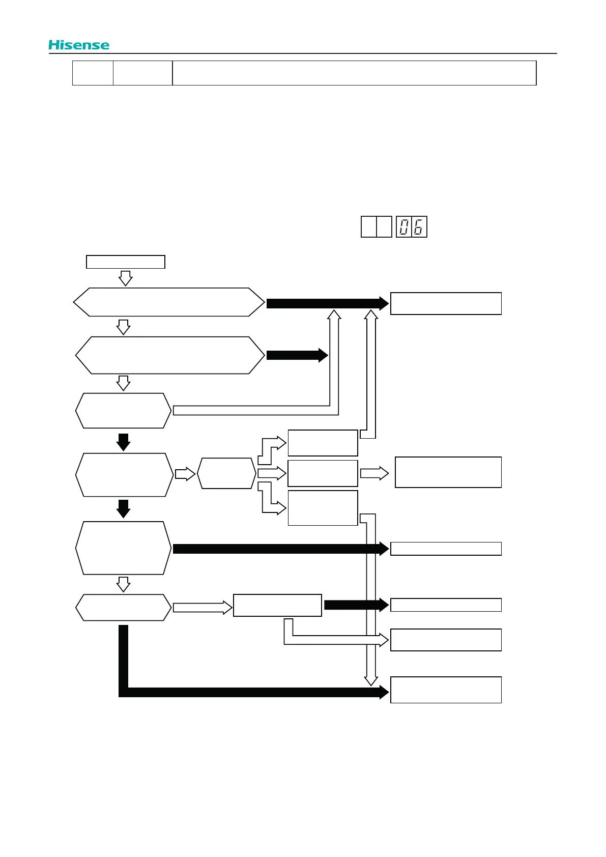
06
Abnormal Inverter Voltage
(Insucient Inverter Voltage or Overvoltage)
● The RUN indicator (Red) is ashing
● The indoor unit number, the alarm code, the unit model code and the connected number of indoor units are displayed on
LCD. Meanwhile, the indoor unit number and the alarm code are displayed on the 7-segment of outdoor unit PCB.
★
This alarm code is indicated when voltage between terminal “P” and “N” of transistor module (IPM) is insucient and this
occurs three times in 30 minutes. In the case that it occurs less than twice, retry is performed.
<Outdoor Unit PCB Display Indication>
Abnormal of Inverter
Yes
Yes
Yes
Yes
Yes
No
No
No
No
No
Restart operation
Is the power supply voltage 208/230V ±10%?
Is the power supply voltage more than 176V?
Does the voltage fall
during operation when
other equipment or
devices are powered on?
Does LED3 on PCB (INV)
ON after compressor’s
relay (RY2) on PCB (INV)
turn ON?
The connections between
inverter PCB (INV), and
reactor (DCL) are correct.
Also, other connections
for inverter PCB (INV) are
correct.
Is the DC voltage
over 192 V?
How is
compressor
operation?
Frequency can
increase higher than
60 Hz
Connect it correctly
Faulty inverter PCB (INV).
Replace it
Normal
Fault
Compressor stops
immediately (lower
than 30 Hz)
Compressor stops
when frequency
increase (approx.
31 Hz to 60 Hz)
Check inverter
PCB (INV)
* Be careful especially because of high voltage
Replace inverter PCB (INV)
careful
Faulty inverter PCB (INV).
Replace it
Check the wiring of
inverter PCB (INV)
PCB have high voltage. Be
Check wiring and wire sizes
No
Yes
 Loading...