189
Troubleshooting
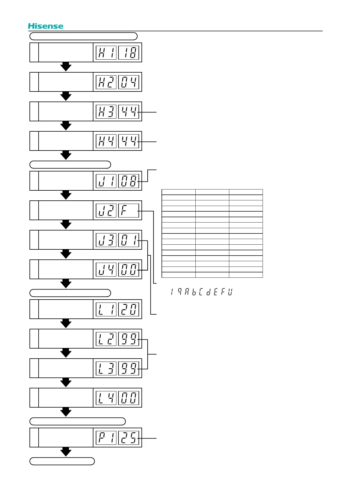
Compressor Pressure/Frequency Indication
20
Discharge Pressure
(High) (x 0.1 psi)
21
Suction Pressure
(Low) (x 0.01 psi)
22 Control Information
23
Fr
Operatio
equency (Hz)
n
25 Outdoor Unit Code
26
Refrigerant Cycle
Number
27
Refrigerant Cycle
Number
24 Indoor Unit Capacity
The total current is indicated when several
compressors are running.
In case of inverter compressor, the running current
of primary side of inverter is indicated.
Capacity Code of Indoor Unit
J3: 01 to 16
(01: when shipment (DSW5), Decimal Indication)
J4: 00 to 0F
(00: when shipment (DSW5), Indication with 16 numbers)
In case of models without Expansion Valve (MV2),
the same figure is indicated.
This is an indication for internal information for the remote
control switch. This does not have any specific meaning.
This is an indication for frequency of Inverter.
The capacity of the indoor unit is indicated as shown
in the table below.
n
Indoor Unit Capacity Indication
Outdoor Unit
Expansion Valve
MV1 Opening (%)
29
Outdoor Unit
Expansion Valve
MV2 Opening (%)
30
Outdoor Unit
Expansion Valve
MVB Opening (%)
31
Indoor Unit
Expansion Valve
Opening (%)
28
Expansion Opening Indication
32
Compressor
Running Current (A)
Estimated Electric Current Indication
Returns to Temperature Indication
Temperature Indication
"n" indicates total number of indoor units;
n = ~
, , , , , , ,
(10) (11) (12) (13) (14) (15) (16)
Indication Capacity (HP) Model (kBtu/h)
4 0.5 05
6 0.8 07
8 1.0 09
10 1.3 12
11 1.5 14
13 1.8 15
14 2.0 17
16 2.3 19
18 2.5 22
20 2.8 24
22 3.0 27
26 3.3 30
32 4.0 38
40 5.0 48
48 6.0 54
 Loading...