230
Servicing
TURN OFF all the power switches.
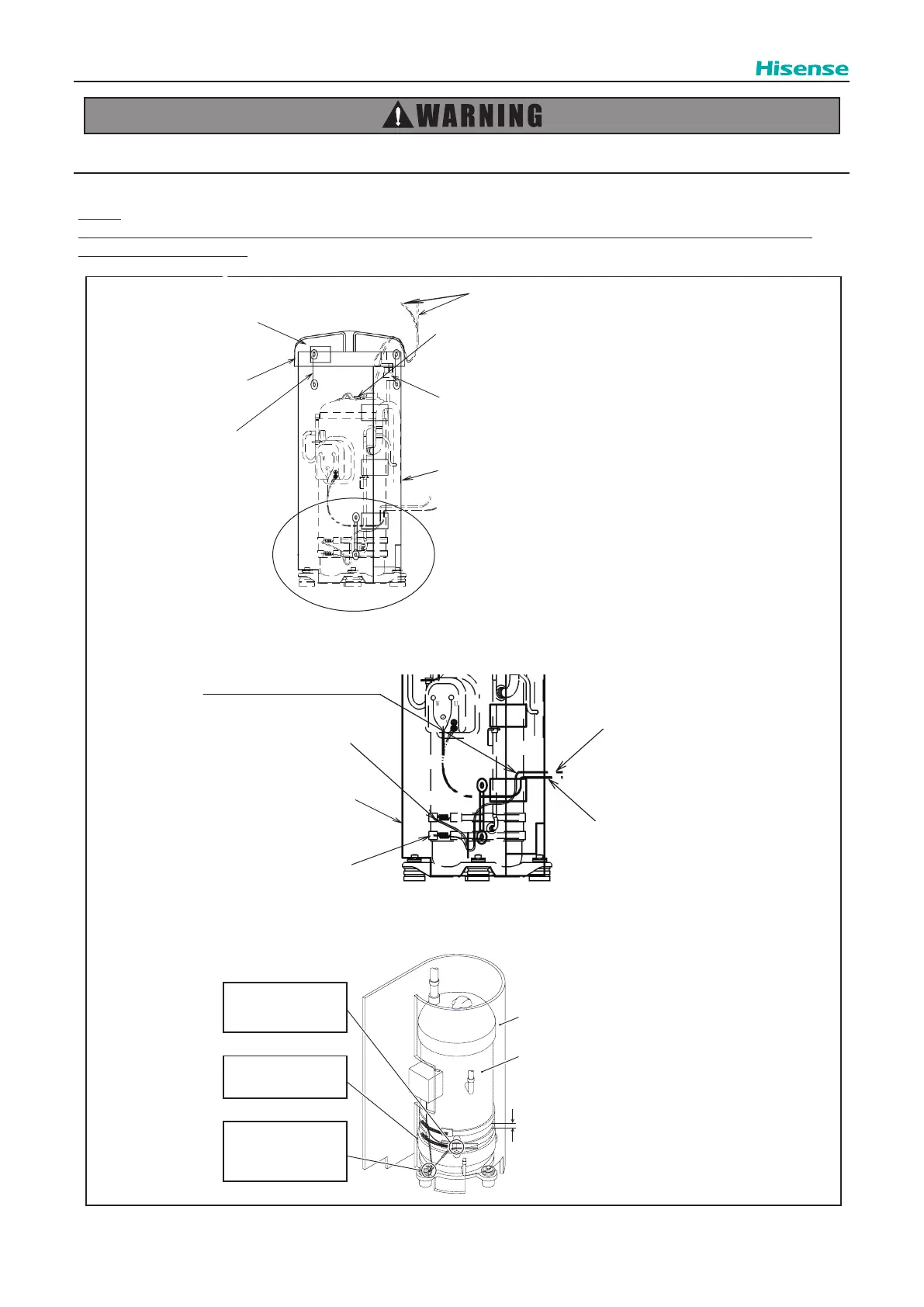
(17) Perform the nal check for wiring conditions referring to the gure below.
NOTE:
Check that all wires do not contact the compressor, piping and plate edges. If any of the wires contacts with them, wire
breakage or re may occur.
(
( )
RC Cover
Power Line for Inverter Comp.
Details View from W
Wind All Bind Lace at
Tack more than 4 times.
Crankcase Heater
Crankcase Heater Position Keep Distance
Approx. 25/32in.(20mm) as Shown in
Figure.
Crankcase Heater Lead Line
PSH (High Pressure Switch)
Crankcase Heater
(
Wind Crankcase Heater on Bottom Cap
as Shown in Figure.
Td Thermistor
Remove Td Thermistor and PSH from Dent Part of RC Cover Right Side.
Slacken Thermistor Wiring and PSH Lead Wire about 25/65in. (10mm) to
Prevent Compressor and Piping from Contacting.
Pull out Power Line for Comp. and
Crankcase Heater Lead Line from
Upper Side of Nylon strap.
Details of Compressor Crankcase Heater Harness Wiring
RC Cover
Compressor
The distance between crankcase heaters
should be Min. 25/32in.(20mm).
Fix compressor power line
and crankcase heater
lead wire together with
a bind lace.
Pull out crankcase heater
lead wire from RC cover
dent part without
contacting with bolt,
nut or pipe of compressor.
Wind crankcase heater
firmly around the
compressor bottom part.
Tack
Fix Sound Proof Cover firmly
to Protect Compressor
from Entering Water.
RC Cover
W
 Loading...