Home
Hisense
Air Conditioner
AVWT-192FFFH
Hisense AVWT-192FFFH User Manual
5
of 1
of 1 rating
317 pages
Give review
Manual
Specs
To Next Page
To Next Page
To Previous Page
To Previous Page
Loading...
242
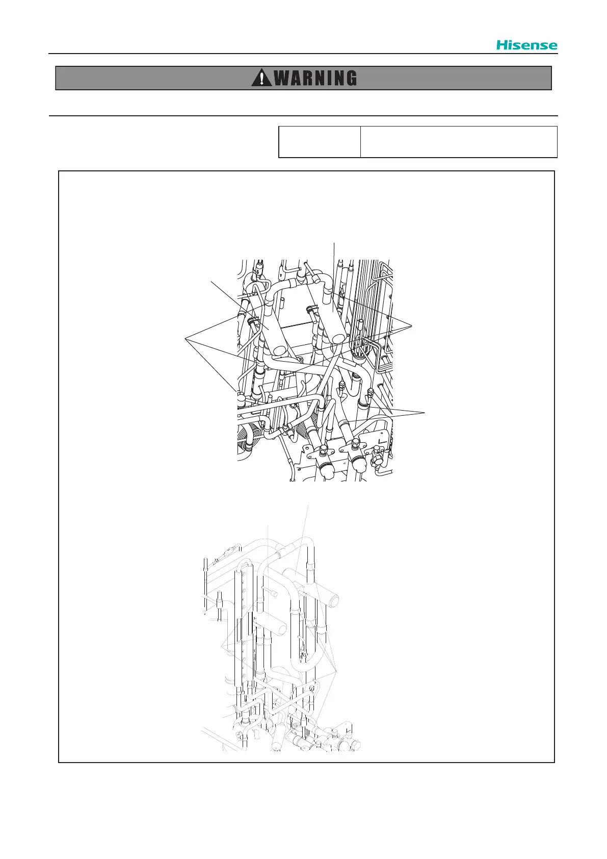
Servicing
TURN OFF all the power switches.
T
ool
Adjustable Wrench or Spanner
,
Phillips Screwdriver
, Burner
, Pipe Cutter
,
Pliers, Pincher
, Charging Hose
<Reversing Valve Position>
●
AVWT-72~96FFFH
●
AVWT-120~192FFFH
RVR1
RVR2
Brazing Part
Brazing Part
Brazing Part
RVR1
RVR1
Brazing Part
Brazing Part
250
252
Table of Contents
Table of Contents
6
Introduction
10
Models of Outdoor Unit
10
Application Case
12
Combination
14
General Data
15
Component Data
21
Safety and Control Device Setting
23
Sound Data
24
Dimensional Data
26
Structure
30
Piping System
34
Connection of Refrigerant Pipes for 3 Pipes Heat Recovery System
34
Connection of Refrigerant Pipes for 2 Pipes Heat Pump System
37
Pipe Connection Design Guidance for 3 Pipes Heat Recovery System
40
Pipe Connection Design Guidance for 2 Pipes Heat Pump System
43
Calculation of Additional Refrigerant
46
Piping Connection Kit Dimensions (Optional)
48
Capacities and Selection Data
54
Procedure for Selection of the System
54
Unique Features of the System
54
Selection Parameters
55
Check Points for System Installation
56
Selection Procedure Example
57
Capacity Correction Based on Refrigerant Piping Length
61
Correction Factor According to Defrosting Operation
63
Control System
64
Refrigerant Cycle
64
Control Logic
67
Standard Operation Procedure Chart
69
Necessary Tools and Instrument List for Installation
81
Outdoor Unit & Refrigeration Cycle
81
Structure
81
Transportation and Handling
83
Transportation
83
Hanging Method
84
Outdoor Unit Installation
85
Service Space
85
Factory-Supplied Accessories
87
Installation
87
Foundation
88
Drain Water Treatment
89
Refrigerant Piping Work
92
Piping Materials
92
Flaring and Joint
93
Caution about Outdoor Unit Installation
94
Piping Connection
96
Stop Valve
97
Piping Connection
98
Electrical Wiring
100
General Check
100
Electrical Data
101
Electrical Wiring Connection
102
DIP Switch Setting of Outdoor Unit
106
Additional Refrigerant Charge
109
Air-Tight Test
109
Vacuuming
109
Charging Operation
110
Test Run
111
Before Test Run
111
Test Run
112
Checking of Rotary Switch and Dip Switch Setting
114
Troubleshooting
114
Checking of Electrical Wiring and Power Supply
114
Initial Troubleshooting
114
Checking by 7-Segment Display
116
Checking of Alarm Code History
117
Troubleshooting
118
Emergency Operation
120
Failure of Power Supply to Indoor Unit and Remote Control Switch
123
Abnormal Transmission between Remote Control Switch and Indoor Unit
124
Abnormalities of Devices
125
Alarm Code Table
133
Troubleshooting Procedure
133
Activation of Protection Device
135
Troubleshooting by Alarm Code
135
Abnormality Transmitting between Inverter PCB and Outdoor Unit PCB
142
Abnormality of Power Supply Phase
145
Decrease in Discharge Gas Superheat
147
Top of Compressor
147
Incorrect Outdoor Unit Address Setting
152
Abnormality of High Pressure Sensor
160
Abnormality of Thermistor for Outdoor Air
161
Incorrect Indoor Unit No. Setting
166
Incorrect Indoor Unit Combination
168
Abnormality of Picking up Circuit for Protection in Outdoor Unit
169
Abnormality of Outdoor Unit Capacity
170
Incorrect Setting of Outdoor Unit Model Combination or Voltage
170
Check Mode
195
Troubleshooting in Check Mode by Remote Control Switch
195
Alarm History Display
201
Troubleshooting by 7-Segment Display
202
Function of RSW, Dsws and Leds
210
Removing Front Service Cover
220
Servicing
220
Attaching Front Service Cover
221
Removing Top Cover
222
Removing Shroud
223
Removing Electrical Box Cover
224
Removing Electrical Box
225
Removing E-Box Stay
226
Removing Air Grille
227
Removing Outdoor Fan
228
Removing Compressor
230
Replacing Refrigerant Oil
240
Replacing Refrigerant Oil (no Clogging in Return Oil Circuit)
240
Replacing Refrigerant Oil (Clogging in Return Oil Circuit) and Replacing Return Oil Circuit
241
Removing Coils
244
Removing Expansion Valve Coil (MV5, EVB, EVO1, EVO2)
246
Removing Solenoid Valve Coil (SVA, SVC, SVG, SVJ, SVS)
247
Removing Solenoid Valve (SVA ,SVC,SVG,SVJ and SVS)
248
Removing Reversing Valve Coil (RVR1, RVR2)
249
Removing Reversing Valve
250
Removing Stop Valve
252
Removing High Pressure Switch, High Pressure Sensor, Low Pressure Sensor and Thermistor
253
Removing High Pressure Switch (PSH1 and PSH2)
255
Removing Thermistor for Liquid Pipe
256
Removing Thermistor for Ambient Temperature
257
Removing Other Electrical Components
258
Removing Outdoor Unit PCB and Electrical Components for Electrical Box
259
Removing Inverter PCB
262
Mount the Electrical Box in the Reverse Procedure
263
Removing Components for Switch Box
264
5
Based on 1 rating
Ask a question
Give review
Questions and Answers:
Need help?
Do you have a question about the Hisense AVWT-192FFFH and is the answer not in the manual?
Ask a question
Hisense AVWT-192FFFH Specifications
General
Brand
Hisense
Model
AVWT-192FFFH
Category
Air Conditioner
Language
English
Related product manuals
Hisense AVWT-76FESRA
269 pages
Hisense AVC-12HJFA
21 pages
Hisense AVC-19HJFA
21 pages
Hisense AVV-17URSCA
28 pages
Hisense AVS-07URCSABA
31 pages
Hisense AVA-30UXCSCH-70
19 pages
Hisense AVA-154UX6SSH-400
20 pages
Hisense AW0621CR1W
17 pages
Hisense AW0823TW1W
45 pages
Hisense AP0621CR1W
36 pages
Hisense AUW-36U4RA4
204 pages
Hisense AP-10CR1SEJS
38 pages
 Loading...