279
Optional Function
4.2.6 Input Low Noise Setting 1, 2, 3 (Control Function No.11 to 13) )
When the input terminals for low noise setting on the outdoor unit PCB are short-circuited, the compressor frequency and
outdoor fan rotation frequency are controlled and the operating sound of the outdoor unit will be given as shown in the table
below.
The operating sound can be set by selecting the control function No.
NOTE:
(a) The outdoor unit capacity will decrease because the compressor frequency and outdoor fan motor frequency forcibly
decrease. The operating range will be also restricted.
(b) In some cases, the operating sound may be temporarily higher than the value in the table below (targeted value).
< Control Function No. for Low Noise Setting and Operating Sound/Outdoor Unit Capacity >
Control Function No. Operating Sound (Target Value)
No Setting Catalog Value
11 (Low Noise Setting 1) Refer to 4.3.7 Low Noise Setting (dB=7)
12 (Low Noise Setting 2) Refer to 4.3.7 Low Noise Setting (dB=8)
13 (Low Noise Setting 3) Refer to 4.3.7 Low Noise Setting (dB=9)
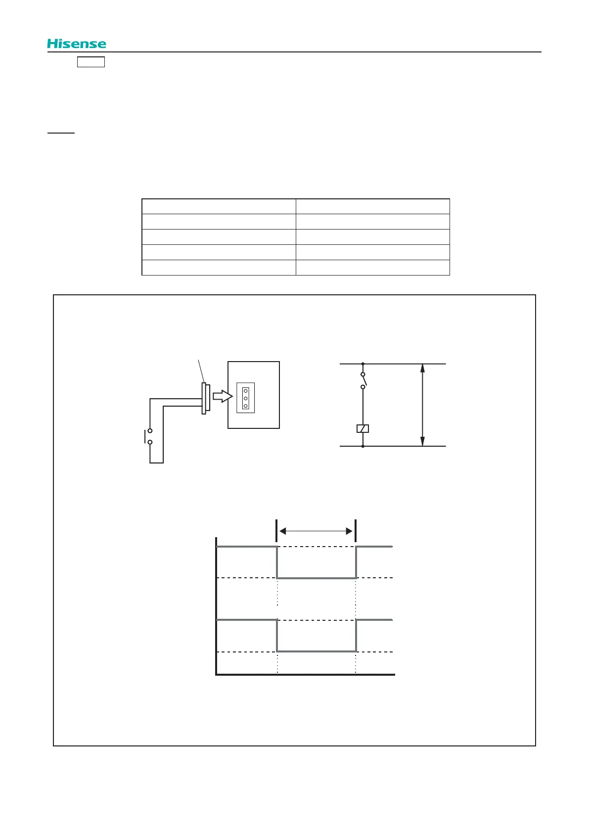
• Setting Example
Low Noise Setting at Input 2 (between 2 and 3 pins of CN17), Control Function No. 12
Control Circuit
Wiring Diagram Example of Low Noise Setting
[Example] “Low Noise Setting 2” during Night Time Only
X1: Auxiliary Relay
SS3: Demand Current Switch
X1
2
3
1
2
3
3P Connector
Outdoor Unit
PCB
CN17
SS3
Power
Supply
X1
Capacity
Operating
Sound
Day Time 20:00 Night Time 8:00 Day Time
Input Terminal
Short-circuited
 Loading...