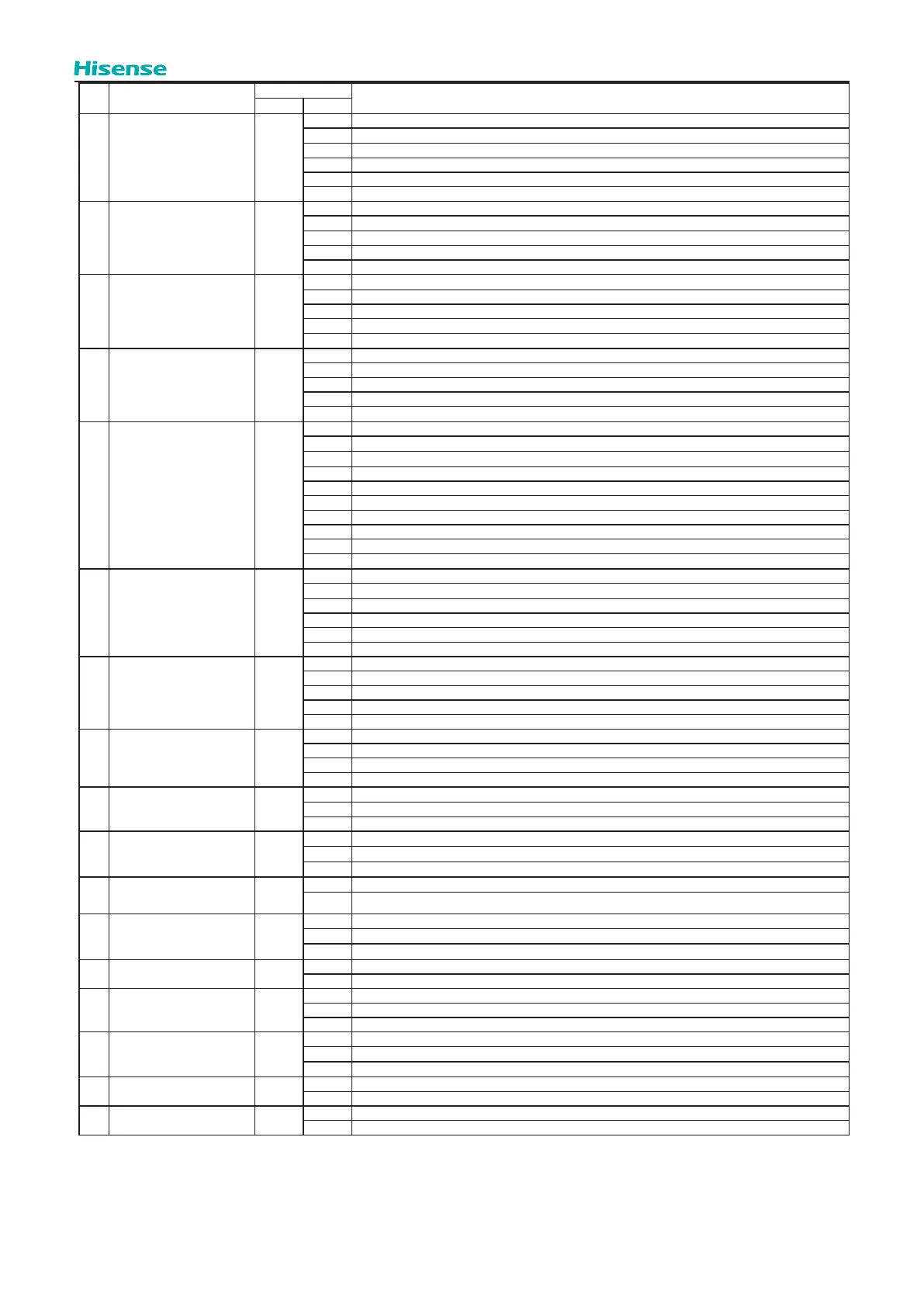
293
Optional Function
No. Setting Item
7-Segment Display
Contents
SEG2 SEG1
15
Initial opening of indoor
expansion valve at heating
operation stoppage
F1
00 Default Setting (refer to control parameters)
01 Expansion valve opening 150~325
02 Expansion valve opening 05~19kBtu/h: 175 pulse, 22kBtu/h or over: 300 pulse
03 Expansion valve opening 05~19kBtu/h: 100 pulse, 22kBtu/h or over: 150 pulse
04 Expansion valve opening 05~19kBtu/h: 90 pulse, 22kBtu/h or over: 100 pulse
05 Expansion valve opening 05~19kBtu/h: 40 pulse, 22kBtu/h or over: 40 pulse
16
Initial opening of expansion
valve in normal control
ci
00 Default Setting(refer to control parameters)
01 Expansion valve opening 300~650
02 Expansion valve opening 05~19kBtu/h: 650 pulse, 22kBtu/h or over: 1000 pulse
03 Expansion valve opening 05~19kBtu/h: 950 pulse, 22kBtu/h or over: 1500 pulse
04 Expansion valve opening 05~19kBtu/h: 1440 pulse, 22kBtu/h or over: 2000 pulse
17
Initial opening ratio of indoor
expansion valve in cooling
start-up control II
cb
00 Default Setting (1.00)
01 Operation initial opening*0.95
02 Operation initial opening *1.03
03 Operation initial opening *1.05
04 Operation initial opening *1.10
18
Initial opening ratio of indoor
expansion valve in heating
start-up control II
ch
00 Default Setting (1.00)
01 Operation initial opening*0.95
02 Operation initial opening *1.03
03 Operation initial opening *1.05
04 Operation initial opening *1.10
19
Low noise setting (In the case
of low noise setting, cooling/
heating operation range will be
restricted.)
db
00 Default Setting
01 Fan rotation maximum - low
02 Fan rotation maximum - lower
03 Fan rotation maximum - lowest
04 Frequency of compressor - low
05 Frequency of compressor - lower
06 Frequency of compressor - lowest
07 Frequency of compressor - low, Fan rotation maximum - low
08 Frequency of compressor - lower, Fan rotation maximum - lower
09 Frequency of compressor - lowest, Fan rotation maximum - lowest
20 Demand function setting dE
00 No demand control
01 Demand control 40%
02 Demand control 60%
03 Demand control 70%
04 Demand control 80%
05 Demand control 100%
21 Wave function setting UE
00 No wave function
01 Minimum limit 40%
02 Minimum limit 60%
03 Minimum limit 70%
04 Minimum limit 80%
22
Low outlet temperature
protection in cooling mode
Fb
00 Default Setting
01 Outlet temperature ≥50°F(10°C)
02 Outlet temperature ≥54°F(12°C)
03 Outlet temperature ≥58°F(14°C)
23
Connection Setting of Fresh Air
Unit or AHU
FT
00 Default Setting
01 Inhibition ability model
02 Compressor Frequency control by indoor unit.
24
Adjustment of fan rotation
(The fan running step must be
over 19-step)
Fo
00 Default Setting
01 Change of fan rotation -15rpm
02 Change of fan rotation -30rpm
25
Setting of height dierence
between Indoor and Outdoor
Units
Hd
00 The height dierence is within the limit
01 The height dierence is out of the limit
26
~
30
Set Address for VIP Indoor Unit
U1
~
U5
0 Indoor unit address 00
~ Indoor unit address **
63 Indoor unit address 63
31 PCB Power Saving Function EC
00 Power saving function OFF, initial setting
01 Power saving function ON
32
Set the quantity of water
modules to be
connected with the system
n3
*1
0
~
15
33
Set the type of water modules
connecting with the system
H4
*2
0 Default setting, water module should be used in a three pipes heat recovery system.
1 — —
2 Water module should be used in a two pipes heat pump system.
34
Capacity setting of indoor unit
and water module
Ui
*3
00 Default setting, capacity balancing of indoor unit (for heating) and water module
01 Capacity of indoor unit for heating enjoys the priority
35
Standby mode setting for
indoor unit when rst power-on
PA
00 Not Available (Default Setting)
01 Forced heating standby of indoor units when SW BOX connected in and ambient temperature
<
76°F(24°C) .
NOTE:
(1)The function setting of “n3” must be set to correct value according to the quantity of water modules connected, otherwise, ALARM 37 may be triggered. (For
example, in case of the quantity of water modules in a system is three, then the value of “n3” should be set to “ “. )
(2)The function setting of “H4” must be set to correct value according to the type of water module connected: H4=0 (default) : water module should be used in a
three pipes heat recovery system.
H4=2: water module should be used in a two pipes heat pump system.
(3)The function setting of “Ui” can be set according to application requirement: Ui=0 (default) : Capacity balance between indoor unit and water module.
Ui=1: Indoor unit will have priority on performance.
 Loading...