297
Field Work Instruction
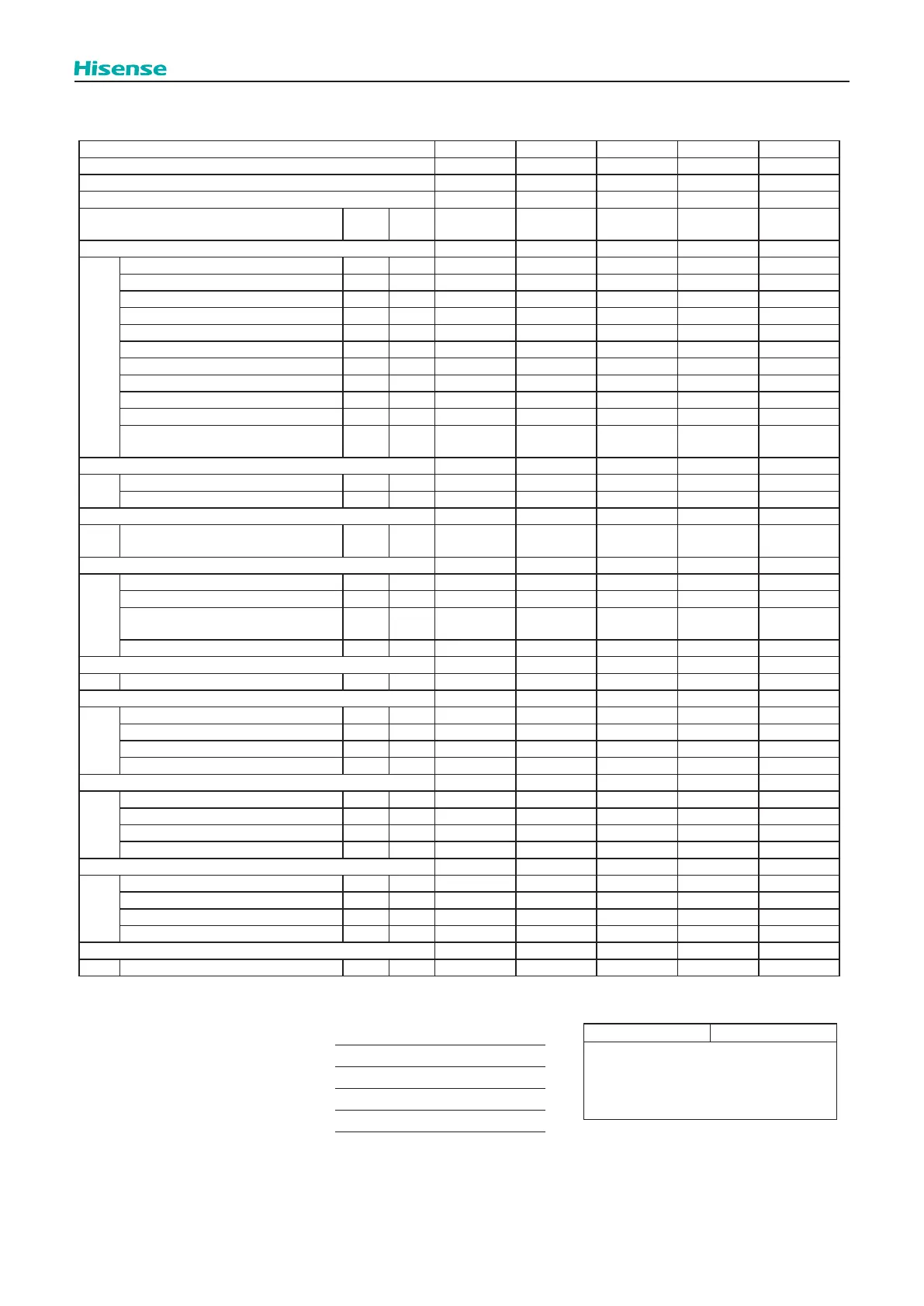
5.4 Service and Maintenance Record by Remote Control Switch
Data Sheet for Checking by Remote Control Switch
Time : : : : :
I.U. Model
I.U. Serial No.
I.U. No. / Alarm Code
Check
Mode 1
Check
Mode 2
1 • 2 1 • 2 1 • 2 1 • 2 1 • 2
B Temp. Indication
Set Temp. b1 - -
Inlet Air Temp. b2 q1
Outlet Air Temp. b3 q2
Liquid Pipe Temp. b4 q3
Remote Thermistor Temp. b5 - -
Outdoor Air Temp. b6 q4
Gas Pipe Temp. b7 q5
Heat Exchanger Coil Temp. of O.U. b8 q6
Number of Running Compressors b9 q7
Comp. Top Temp. bA q8
Thermo Temp. of Remote Control
Switch
bb - -
C Micro-Computer State Indication
I.U. Micro-Computer C1 - -
O.U. Micro-Computer C2 - -
D Stopping Cause State Indication
Stopping Cause
State Indication
d1 - -
E Alarm Occurrence
Times of Abnormality E1 - -
Times of Power Failure E2 - -
Times of
Abnormal Transmitting
E3 - -
Times of Inverter Tripping E4 - -
F Automatic Louver State
Louver Sensor State F1 - -
H Pressure, Frequency State Indication
Discharge Pressure H1 q9
Suction Pressure H2 qA
Target frequency H3 qb
Operating Frequency H4 qC
J I.U. Capacity Indication
I.U. Capacity (X1/8HP) J1 - -
O.U. Model Code J2 - -
Refrigerant Cycle Number J3 - -
Refrigerant Cycle Number J4 - -
L Opening of Expansion Valve
I.U. Expansion Valve L1 qd
O.U. Expansion Valve 1 L2 qE
O.U. Expansion Valve 2 L3 - -
O.U. Expansion Valve B L4 - -
P Running Current Indication (Reference)
Comp. Current P1 qF
Client:
Installation Date:
System No.:
Date Checked:
Checked by:
Result
 Loading...