59
Control System
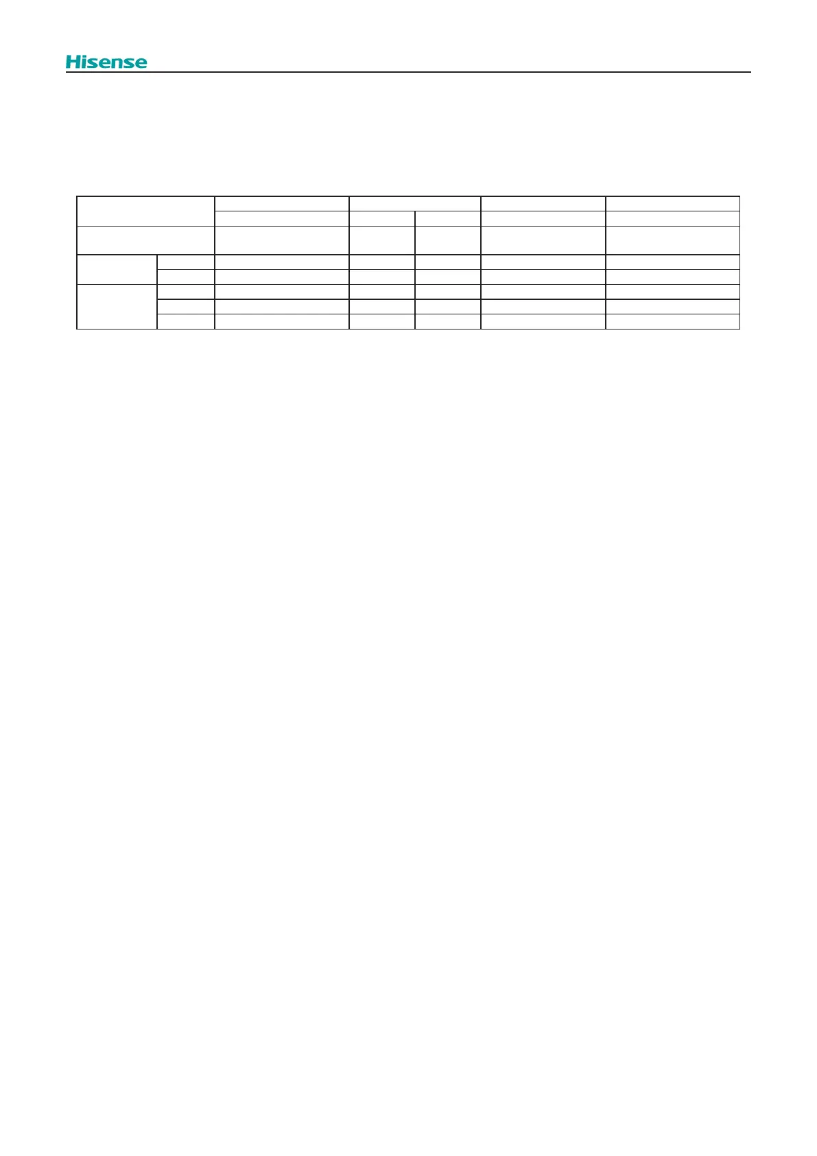
(2) Heat Exchanger Mode Control
In accordance with the connectable indoor unit operation mode, the outdoor unit heat exchanger is switched as shown in
the table below.
Heat Exchanger Mode at Cooling: Condenser COND
Heat Exchanger Mode at Heating: Evaporator EVAP
The Number of Outdoor Unit: 1 (one)
Heat Exchanger Mode
Cooling Mode Mainly Cooling Mode Mainly Heating Mode Heating Mode
COND D1 D1-1 D4 EVAP
Heat Exchanger
Condition
COND COND cond EVAP EVAP
Reversing
Valve
RVR2 OFF OFF OFF ON ON
RVR1 ON OFF OFF OFF OFF
Expansion
Valve
EVO HEX SC HEX SC-Pd HEX SC-Pd HEX SH HEX SH
MV5 Tf Tf Tf Tf Tf
EVB Td-SC Td-SC Td-SC Td-SC Td-SC
NOTE:
(1) Heat Exchanger Condition
COND : Use as Condenser
cond : Avoid the use of Heat Exchanger (under a high pressure condition)
EVAP : Use as Evaporator
(2) Control Method of Expansion Valve
HEX SC: To adjust to achieve the target value of heat exchanger SC
HEX SH: To adjust to achieve the target value of heat exchanger SH
Pd: To adjust to achieve the target value of Discharge Pressure
Tf: To adjusted to suppress Inverter Temperature increase
Td-SC: To adjusted to achieve the target value of compressor discharge temperature and SC of liquid refrigerant
.
(3) COND, D1, D1-1, D4 and EVAP are the reference numbers.
 Loading...