1. GETTING STARTED
1-15
Table 1-2 Dimension, Service Clearance, and Installation Clearance
Dimension (mm)
Operation and
service clearance (mm)
Installation clearance (mm)
Height Width Depth Front Rear Left Right Front Rear Left Right
93 325 356
500 600 200 200 50 100 10 10
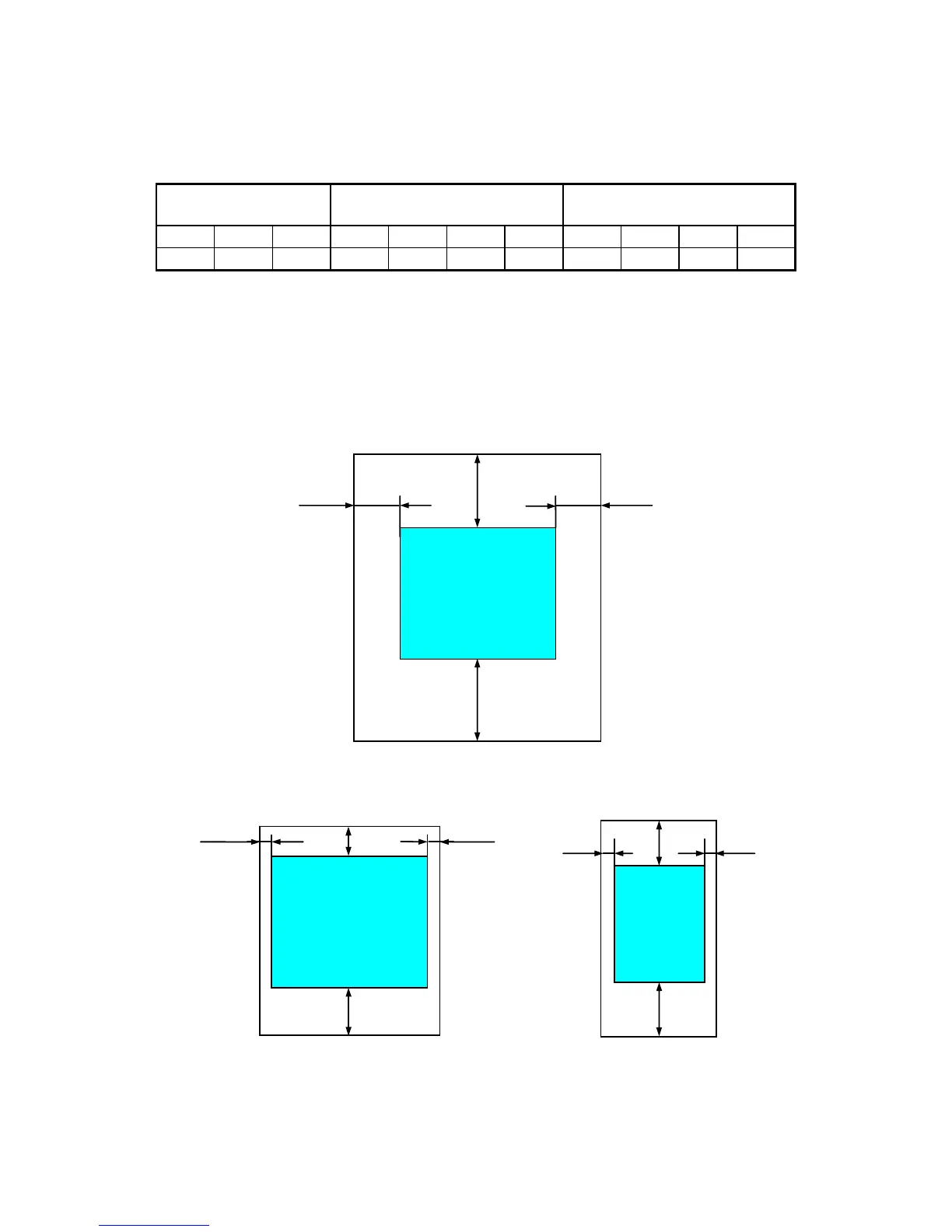
・When you operate the equipment or do maintenance work, provide sufficient clearance
as shown in Figure 1-1.
・The equipment is air-cooled by fans. The intake holes are on the front and the exhaust
holes are on the rear. Make sure the air flow is not blocked. Especially, leave sufficient
clearance in the front (50 mm) and in the rear (100mm). (This includes clearance required
for routing cable connectors for the rear side.)
Figure 1-4 Operation and Service Clearance (Top View)
Figure 1-5 Installation Clearance
200 mm 200 mm
Front side
Rear side
600 mm
500 mm
Vertical Installation (Top View)
100 mm
50 mm
10 mm
10 mm
Front side
Rear side
Horizontal Installation (Top View)
100 mm
10 mm
50 mm
10 mm
Front side
Rear side