OPERATOR'S STATION
1-32
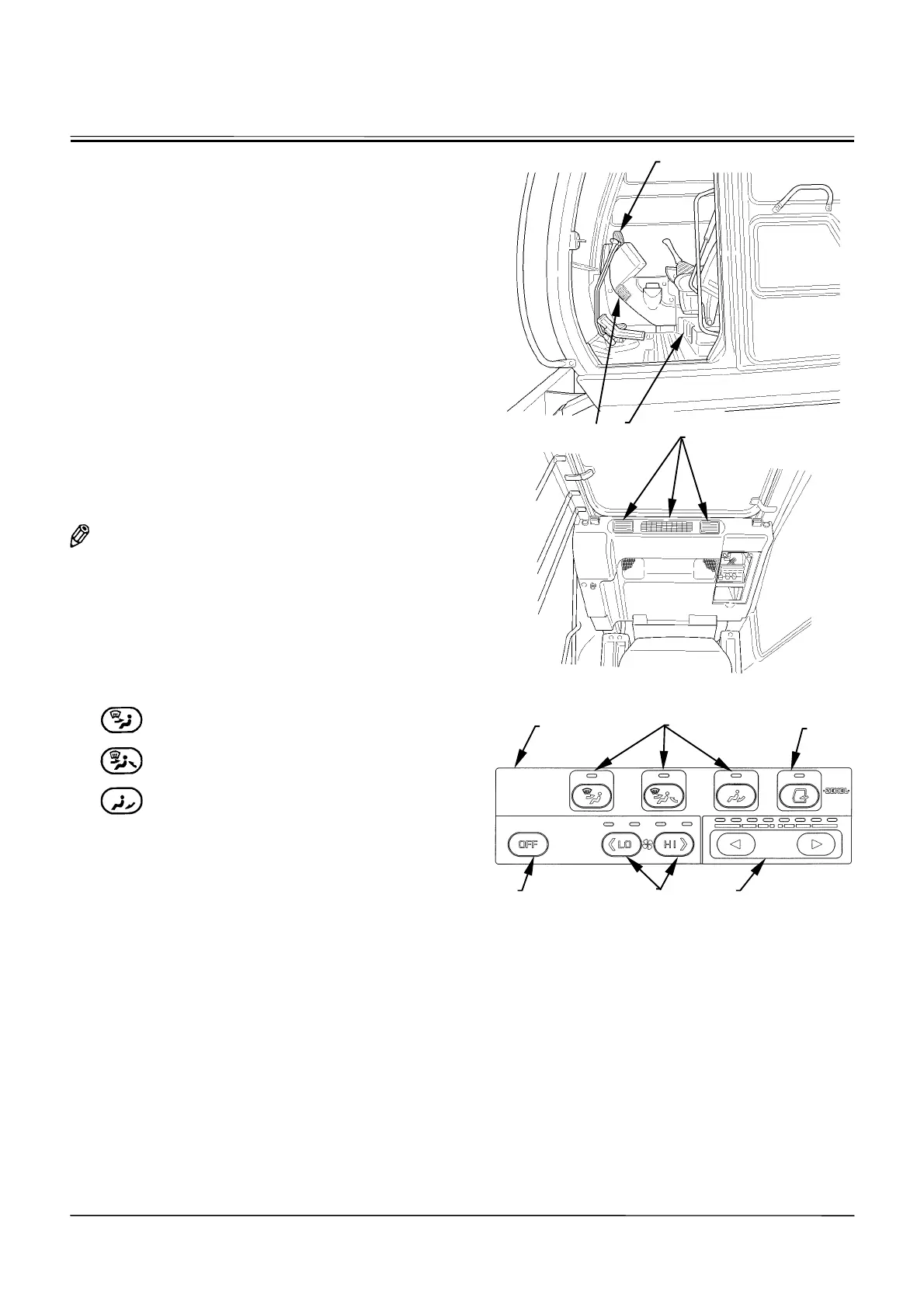
CAB HEATER (Optional)
Part Name and Location
1- Front Vent
2- Foot Vent
3- Defroster Vent
4- Rear Vent
5- Control Panel
6- Mode Switch
7- Fresh Air Vent Switch
8- Temperature Control Switch
9- Blower Switch
10- OFF Switch
NOTE: Air flow direction can be changed by controlling
the louvers at all air vents except for the foot
vents. The louvers at the front and defroster
vents can be manually opened or closed.
Control Panel Designation and Function
•
Mode Switch (6):
Selects the air vent.
Air flows out of the front vents and the
defroster vents.
Air flows out of the front and rear vents
and the defroster vents.
Air flows out of the foot vents.
Temperature Control Switch (8)
One of 8 indicators is lit. The air flow temperature at the
vent is lower or higher as the indicator closer to the left or
right end is lit respectively. Both warmed and cooled air
flow out of the same air vent.
M1CC-01-017
M1CC-01-018
M178-01-072
1
2
3
4
6
7
5
8
9
10