5. Configuration and Function of Internal Memory
5.5. PUT/GET function block use area (parameter area)
R200 Analog Input Module 2MLF-AV8A, AC8A User's Guide 99
September 2010 Honeywell
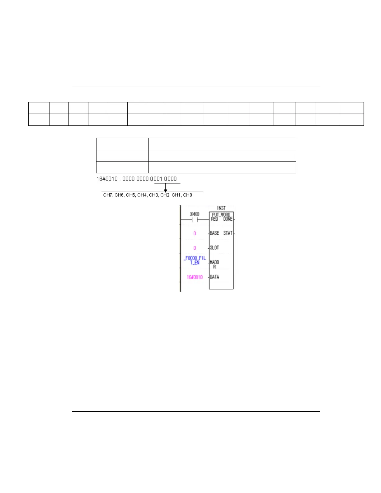
B15 B14 B13 B12 B11 B10 B9 B8 B7 B6 B5 B4 B3 B2 B1 B0
- - - - - - - - CH7 CH6 CH5 CH4 CH3 CH2 CH1 CH0
BIT Description
0 Disable
1 Enable
Filter constant setting
1. Initial value of filter constant is 1.
2. Setting range of filter constant is 1~99.
3. When setting value other than setting range, it indicates error number 50# at error
code indication address (22). At this time, A/D conversion value keeps previous
data. (# means the channel where error occurs at error code.)
4. If filter constant is not set; filter constant is set as ‘1’.
5. The following figure is an example for setting filter constant as 9 at channel 0.
 Loading...


