CLSS Gateway - Installation and Users’ Manual | P/N:LS10248-000HW-E | REV. F | FEB/11/2022 64
Register Mapping Modbus Communications
7.22.4 Zones/Panel Circuits Status Holding Registers
Each of the zones/panel circuits status holding registers are divided into an upper and
lower byte as described below.
• Upper Byte: The upper byte contains general status information about the zone or
panel circuit.
• Lower Byte: The lower byte is primarily used when bit 11 in the upper byte is a ‘1’ (or
active). When bit 11 is a ‘1’, See “CLSS Gateway Active Event Code” on page 74.
for detailed information about the active zone or panel circuit. The lower byte will be all 0’s
if the zone/panel circuit is not in an active state.
Specifically, the lower byte contains the actual active event for this zone or panel circuit.
An active state is defined in this gateway as any Fire, Security, Critical Process, Medical,
Mass Notification, or Supervisory alarm state.
If the zone or panel circuit is not present in the panel programming, all bits in the lower
byte will contain a ‘1’ or the value ‘FFH’, but the upper byte will contain a ‘0’.
The holding register addresses and the zones contained in these addresses are detailed
in this table.
The holding register addresses and the panel circuits contained in these addresses are
detailed in Table 7.15, “Panel Circuits”.
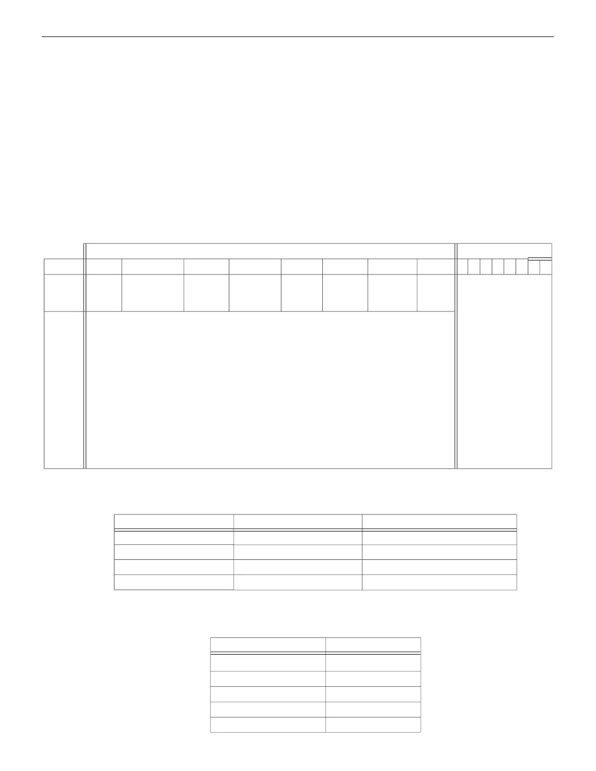
Table 7.13: Zones/Panel Circuits Holding Register Bit Definitions
Upper Byte Lower Byte
Bit No. 15 14 13 12 11 10 9 8 7 6 5 4 3 2 1 0
Bit
Name
Ack
Block
Prealarm Trouble InActive Active Enable Disable
Ack
Fire
Alarm
Active Event Type
(When Bit 11 is
set to 1, see
7.30
"CLSS Gateway
Active Event Code"
.)
When individual upper byte bits are set to 1, the following definitions apply:
Ack Block (Bit 15): All events on this zone/panel circuit, other than fire
alarm, are acknowledged.
Prealarm (Bit 14): The zone/panel circuit is in a prealarm state.
Trouble (Bit 13): The zone/panel circuit is in a trouble state.
InActive (Bit 12): The zone/panel circuit is not active.
Active (Bit 11): The zone/panel circuit is active and there will be an active
event type in the lower byte.
Enable (Bit 10): The zone/panel circuit is enabled.
Disable (Bit 9): The zone/panel circuit is disabled.
Ack Fire Alarm (Bit 8): The fire alarm on this zone/panel circuit is
acknowledged.
Table 7.14: Zones
Zone Type Register Address Zone Address
General Zones 408001–410000 Z 1,2,3,4,5,6,7,8,...2000
Logic Zones 410001–412000 Z 1,2,3,4,5,6,7,8,...2000
Trouble Zones 412001–412100 Z 1,2,3,4,5,6,7,8,...100
Releasing Zones 412101–412200 Z 1,2,3,4,5,6,7,8,...100
Table 7.15: Panel Circuits
Register Address Panel Circuits
414001–414008 P1.1–P1.8
414009–414016 P2.1–P2.8
414017–414024 P3.1–P3.8
414025–414032 P4.1–P4.8
414033–414040 P5.1–P5.8

 Loading...


