CLSS Gateway - Installation and Users’ Manual | P/N:LS10248-000HW-E | REV. F | FEB/11/2022 107
Supported Panels Connecting to the Panels
C.2 Supported Panels
The CLSS Gateway supports the following panel variants:
• AM Series Panels
• ESSER Panels
• Farenhyt Panels
• FireWarden Panels
• Gamewell-FCI Panels
• Gent Panels
• Morley-IAS Panels
• NOTIFIER® UL
• NOTIFIER® European Panels (EN)
• Silent Knight Panels
• Triga Panels
• VESDA® Detectors
C.3 AM Series Panels
C.3.1 Connection Options
The gateway operates only with the AM Series fire alarm control panels listed in the table
below:
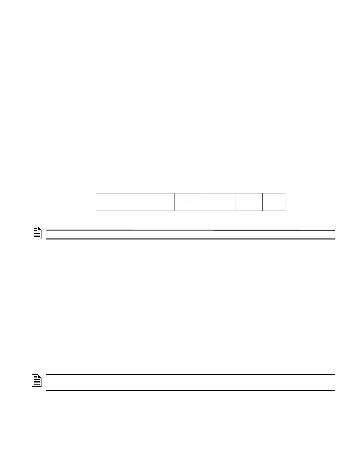
Table C.1: AM Series Panel Connection Options
Minimum Required Versions
For the Panel/CPU1: v1.0.703 | For SIB version Panel: v0.68
For the CLSS Gateway: 3.0.4.56
C.3.2 To Use an RS-232 Connection
Using an RS-232 cable the CLSS Gateway and the panel are connected.
The RS-232 port in the gateway board is labeled as 6 in the Figure C.2.
1. On the Gateway Side
Connect to an RS-232 port of the gateway board.
2. On the Panel Side
• AM8200 Panels
• AM8200 Panels
• Connect the White wire to the RX pin of the SIB 8200 board.
• Connect the Green wire to the GND pin of the SIB 8200 board.
• Connect the Brown wire to the TX pin of the SIB 8200 board.
Fire Alarm Panel Models RS-485 UART/TTL RS-232 USB
AM8200
No No Yes
1
1 Use the SIB 8200 board
No
NOTE: The panel can be a stand alone panel or part of a network of panels.
NOTE: Because the SIB 8200 board on the panel connects to the gateway, the SIB board
cannot be used for printing the events.

 Loading...


