CLSS Gateway - Installation and Users’ Manual | P/N:LS10248-000HW-E | REV. F | FEB/11/2022 67
Analog Values Input Registers Modbus Communications
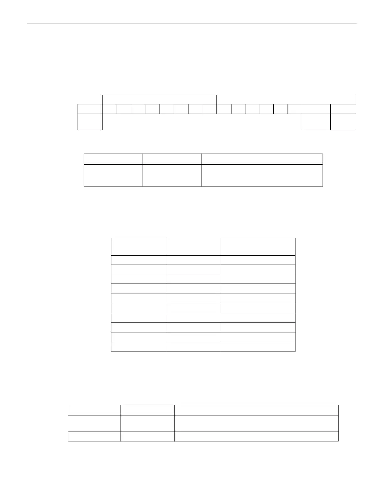
7.22.7 Panel Status Holding Register
The panel status holding register is divided into an upper and lower byte as described
below and in Table 7.21, “Panel Status Holding Register Bit Definitions” representing one
register address as shown in Table 7.22, “Panel Status Holding Register Addresses”.
• Silence: The fire alarm control panel is silenced when this bit is set to 1.
• Reset: Not used.
Table 7.21: Panel Status Holding Register Bit Definitions
7.23 Analog Values Input Registers
Analog values listed in Table 7.23, “Input Register Analog Values” are only available for 4–
20 mA modules. Refer to Table 7.23, “Input Register Analog Values” for details regarding
analog values.
7.23.1 Panel and System Troubles Holding Registers
One hundred 16-bit registers are reserved for panel troubles and one register is assigned
as an overall panel trouble indicator as shown in Table 7.24, “Panel and System Troubles
Holding Register Addresses”.
A single bit is reserved for each trouble in the system. The assignment of bits to trouble
codes is shown in
Table 7.33: "System Troubles Register Map".
Upper Byte Lower Byte
Bit No.
15 14 13 12 11 10 9 8 7 6 5 4 3 2 1 0
Bit
Name
Not Used
Silence Reset
Table 7.22: Panel Status Holding Register Addresses
Start Address End Address Description
420001 420001 Panel Status Holding Register
Table 7.23: Input Register Analog Values
Start Address End Address
Analog Value
(16 bits)
310001 310300 L1M1–L1M300
310301 310600 L2M1–L2M300
310601 310900 L3M1–L3M300
310901 311200 L4M1–L4M300
311201 311500 L5M1–L5M300
311501 311800 L6M1–L6M300
311801 312100 L7M1–L7M300
312101 312400 L8M1–L8M300
312401 312700 L9M1–L9M300
312701 313000 L10M1–L10M300
Table 7.24: Panel and System Troubles Holding Register Addresses
Start Address End Address Description
460000 460000
Panel Trouble Summary
(Total number of Trouble bits set for the node)
460001 460100 Panel Troubles

 Loading...


