CLSS Gateway - Installation and Users’ Manual | P/N:LS10248-000HW-E | REV. F | FEB/11/2022 141
NOTIFIER® European Panels (EN) Connecting to the Panels
C.11 NOTIFIER® European Panels (EN)
C.11.1 Connection Options
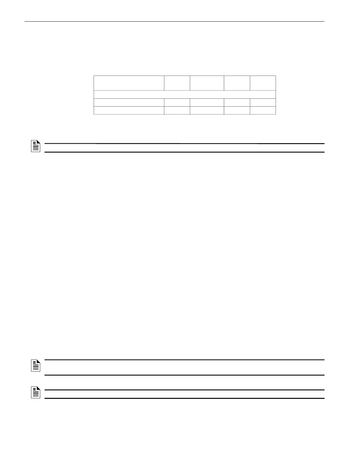
The gateway operates only with the NOTIFIER fire alarm control panels listed in the table
below:
Table C.9: NOTIFIER European Panel Connection Options
C.11.2 Preparing for Connections
For INPIRE panel power connection, you can use either a serial card or an I/O card.
• Configure the serial card or the I/O card for the power connection at the Serial
Communication screen of the CLSS Fusion Tool Suite.
• Configure the communication settings at the Serial Communication screen of the
CLSS Fusion Tool Suite.
C.11.3 To Use a NUP Connection
Some NOTIFIER panel variants use a NUP connection with the CLSS Gateway.
1. On the Gateway Side
Connect the NUP cable with a pre-formed connector to the NUP port of the gateway
board.
Refer to Figure C.2 where the NUP port is labeled as 6. It is the P7 pin on the gateway
board.
2. On the Panel Side
• INSPIRE Panels
• INSPIRE Panels
In the serial communication card on the panel:
• Connect the White wire to the pin 9 (CH2 RX/B).
• Connect the Green wire to the pin 8 (CH2 ISO GND).
• Connect the Brown wire to the pin 10 (CH2 TX/A).
3. Power Connection
The gateway can receive its power either from an external power source or from the
non-resettable internal power of the panel.For the External Power Supply:
Fire Alarm Panel Models RS-485 UART/TTL
NUP
(RS-232)
USB
INSPIRE Fusion Panels
E10 No No Yes
1 o r 2
1 Use the serial communication card (P/N: HOP-405-100) on the
panel.
2 Use the I/O card (P/N: HOP-404-100) on the panel.
No
E15 No No Yes
3 o r 4
No
<
NOTE: Compatible CLSS Gateway firmware versions: 3.0.2.30 and above.
NOTE: The external power supply must be dedicated and not shared with any other
devices.
NOTE: The panel’s power supply to the gateway must be within +24V DC power.

 Loading...


