CLSS Gateway - Installation and Users’ Manual | P/N:LS10248-000HW-E | REV. F | FEB/11/2022 134
Gent Panels Connecting to the Panels
3. Power Connection
On the Gateway Side
1. Connect to the 24V DC external power supply.
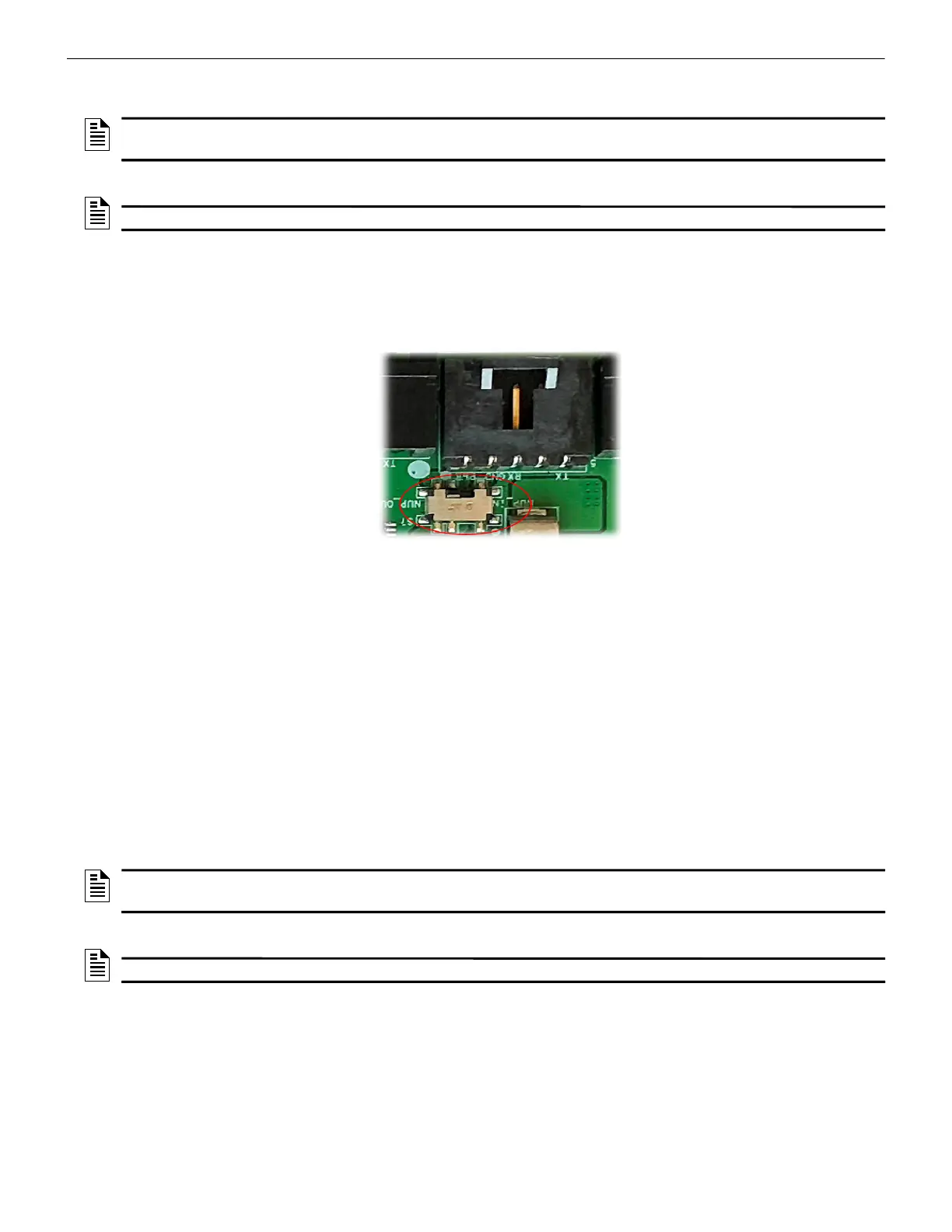
2. Ensure that the S7 switch next to the RS-232 port is switched towards NUP_OUT.
Figure C.21: The S7 Switch
On the Panel Side
Connect the power cable into the 24V DC external power supply.
To Use a USB Connection
1. On the Gateway Side
Connect the USB-C side of the cable to the USB port of the gateway.
The USB port is labeled as 8 in the figure Figure C.2.
2. On the Panel Side
In the MCC card on the panel:
Connect the USB-B side of the cable. Refer to the figure Figure C.20.
3. Power Connection
Connect the gateway to a 24V DC external power source.
NOTE: The external power supply must be dedicated and not shared with any other
devices.
NOTE: The panel’s power supply to the gateway must be within +24V DC power.
NOTE: The external power supply must be dedicated and not shared with any other
devices.
NOTE: The panel’s power supply to the gateway must be within +24V DC power.

 Loading...


