CLSS Gateway - Installation and Users’ Manual | P/N:LS10248-000HW-E | REV. F | FEB/11/2022 71
Conversion to Modbus RTU Modbus Communications
7.27.2 Software Configuration
Configure the CLSS Gateway as a node in the NFN network with a node number.
Refer to the NOTI•FIRE•NET™ Network Systems Interface Manual (P/N 51584) or the High
Speed NOTI•FIRE•NET™ Instruction Manual (P/N 54013) for details about network
configuration.
When configuring the network, refer to the settings specified in
Table 7.28: "MGate
MB3180 Configuration Settings"
. Settings not specified should be tailored to your network
requirements. Refer to the MGate MB3000 Modbus Gateway User’s Manual for details.
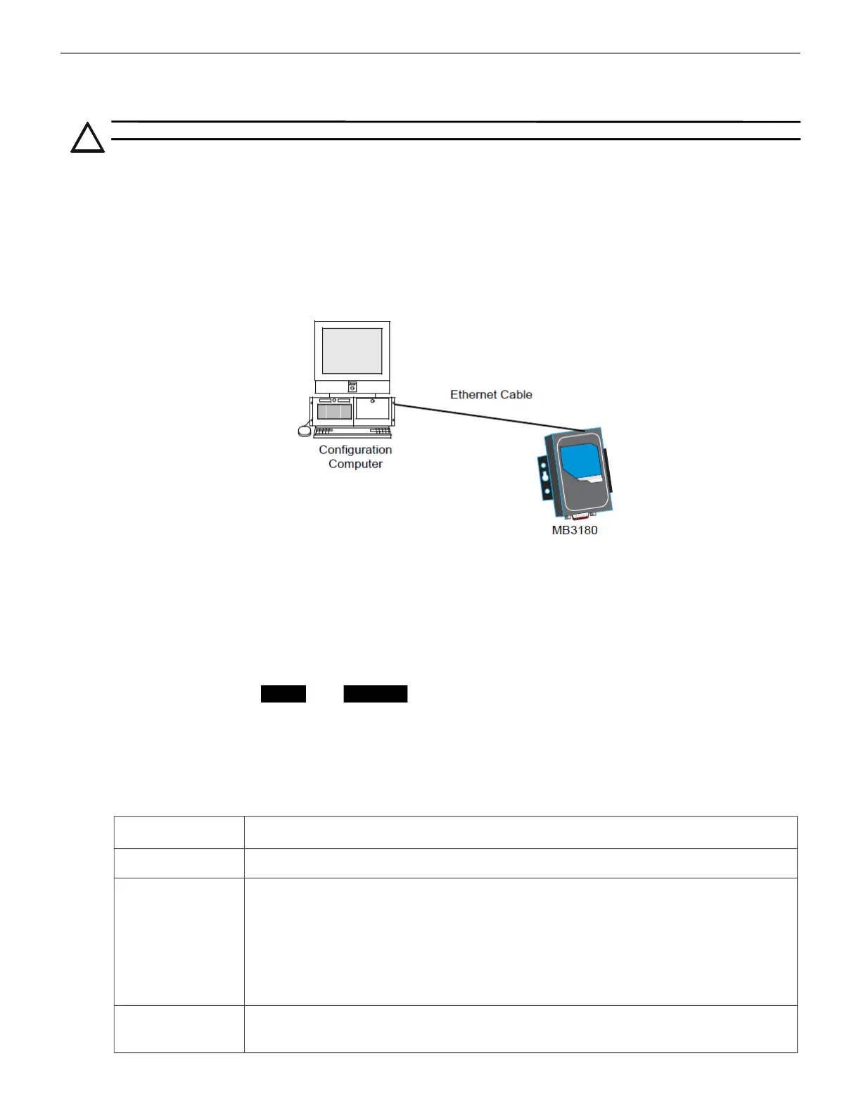
1. Connect the MB3180 to a configuration computer through an Ethernet cable as
shown in
Figure 7.7.
Figure 7.7: Connect a Configuration Computer
2. Run the MGate Manager installation software (
MGM_SETUP_VERX.X_BUILD_XXXXXXXX.EXE
)
found on the Software CD shipped with the MGate MB3180.
3. Wait for the installation to complete.
4. Run MGate Manager.
5. Power up the MB3180.
6. Ensure that the
Ready and Ethernet lights are ON.
7. Configure the MB3180 for the network.
8. Wait for the configuration to complete.
9. Click OK.
10.Click Exit.
CAUTION: ENSURE THAT THE NFN NETWORK CONFIGURATIONS ARE UNCHANGED.
Table 7.28: MGate MB3180 Configuration Settings
Tab Setting
Mode RTU Master Mode
Slave ID Map
The MGate MB3180 accepts the Modbus Unit ID as a virtual slave ID and
monitors devices with these virtual slave IDs.
By default, the CLSS Gateway assigns a Modbus Unit ID to each node on the
NFN network. The ID is equal to node number of the node. They can be
changed, but should be within 1 to 99.
Refer to the
7.17 "To Configure the Modbus Settings" section for more
information about changing a Modbus Unit ID.
Modbus
Initial Delay: 0 ms
Response Time-out: 1000 ms

 Loading...


