CLSS Gateway - Installation and Users’ Manual | P/N:LS10248-000HW-E | REV. F | FEB/11/2022 125
Gamewell-FCI Panels Connecting to the Panels
C.7 Gamewell-FCI Panels
C.7.1 Connection Options
Each variant of the Gamewell-FCI panel offers various connection options.
The gateway operates only with the Gamewell-FCI fire alarm control panels listed in the
table below:
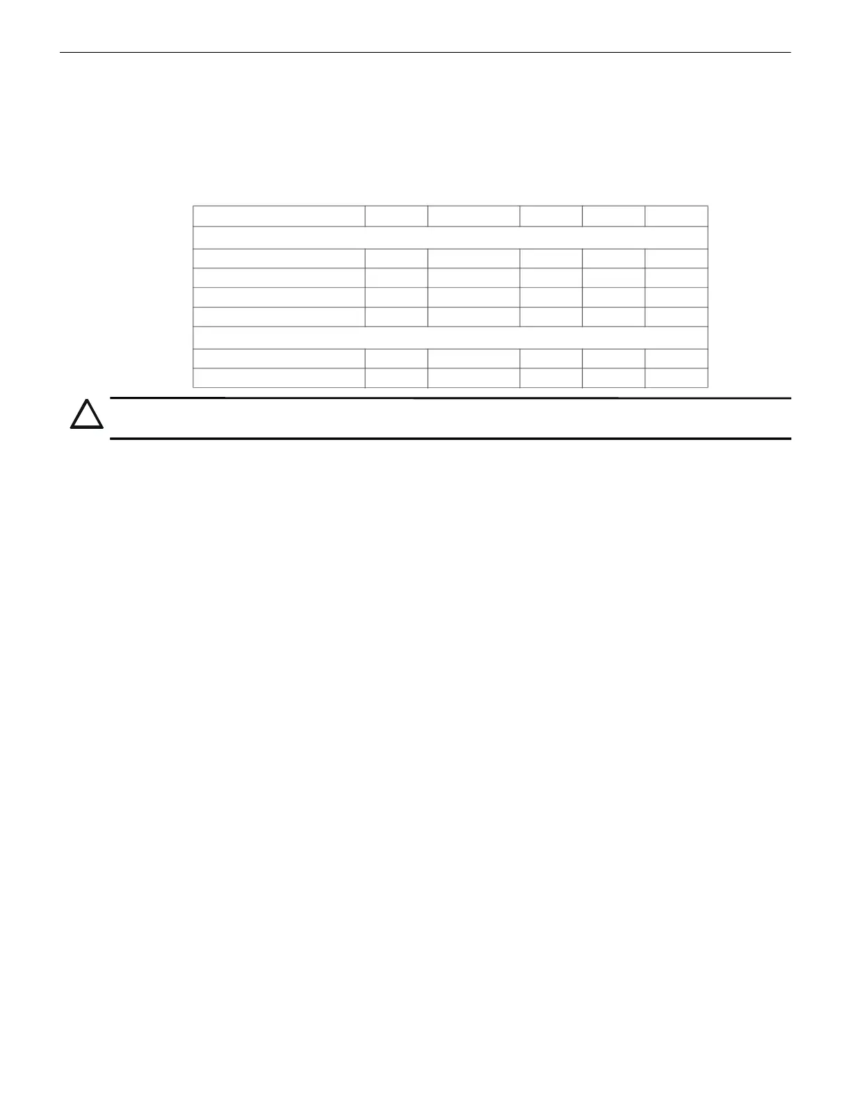
Table C.5: Gamewell-FCI Panel Connection Options
Minimum Required Versions
Gamewell-E3: 7.00.106
Gamewell-S3: 7.00.106
CLSS Gateway: 3.1.4.72
LCD-SLP (Display Panel): 2.12.090
NGA-K: 7.00.100
Limitation(s)
Support for CAM-event alerts is currently not available for the CLSS Gateway. When the
support is available, the CLSS Gateway will send these messages to CLSS Site Manager
(Cloud) and the CLSS App.
C.7.2 To Use Panel’s Printer Port Connection
Gamewell panels support data transfer through their RS-485 connection. The transferred
data is stored in the CLSS Site Manager.
1. On the Gateway Side
1. Connect the + (24 V) wire to the IN+ pin of an RS-485 port.
2. Connect the - (GND) wire to the IN- pin of an RS-485 port.
The RS-485 ports are labeled as 3 and 4 in the Figure C.13.
2. On the Panel Side
• E3 Series Panel
• S3 Series Panel
• E3 Series Panel
At the TB3 terminal of the panel,
• Connect the +ve wire to the TB3-1 pin.
• Connect the -ve wire to the TB3-2 pin.
At the TB6 terminal of the panel,
• Connect the GND wire to the TB6-1 pin.
• Connect the TxD wire to the TB6-2 pin.
• Connect the SUPV wire to the TB6-3 pin.
Fire Alarm Panel Models RS-485 UART/TTL RS-232 USB Ethernet
E3 Series Panels
ILI-MB-E3 Yes No No Yes No
ILI-S-E3 No No No Yes No
ILI95-MB-E3 Yes No No Yes No
ILI95-S-E3 No No No Yes No
S3 Series Panels
SLP-E3 Yes No No Yes Yes
INI-7100 Yes No No Yes No
CAUTION: DO NOT INSTALL DACT-E3 AND THE CLSS GATEWAY TOGETHER ON AN ILI-MB-E3 CIRCUIT
BOARD OR AN ILI95-MB-E3 CIRCUIT BOARD. YOU CAN USE DACT-E3 ON A DIFFERENT NODE WITHIN
THE NETWORK.

 Loading...


