CLSS Gateway - Installation and Users’ Manual | P/N:LS10248-000HW-E | REV. F | FEB/11/2022 18
CLSS Gateway Parts Overview
2.3.3 Switches on the Gateway Board
Below table informs about the switches on the gateway board. To locate the switches on
the gateway board, refer to Figure 2.1:, "Printed Circuit Board: Layout".
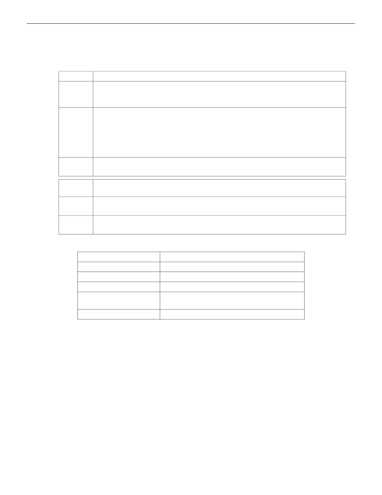
Table 2.3: Gateway Board Switches
2.4 CLSS Gateway Parts
Switches Purpose
S6
For securely configuring the gateway’s settings
Pressing the switch for six seconds switches the gateway board to the
configuration mode.
S7
For changing the direction of the 24V power of the NUP/RS-232
connector
NUP_IN: The gateway board receives power through its NUP/RS-232
port.
NUP_OUT: The gateway board receives power through its power supply
port, which is connected to an external power supply source.
S8
For enabling mobile pairing
Pressing the switch for ten seconds enables mobile pairing.
Tamper
Switches
Purpose
Tamper 1
For alerting whenever the gateway enclosure door is opened
It is located at the front-side of the gateway, next to the LED indicators.
Tamper 2
For alerting whenever the gateway board is removed from the enclosure
It is located at the backside of the gateway.
Part Number Description
HON-CGW-MBB CLSS Gateway with enclosure
CGW-MB CLSS Gateway board
CGW-BB CLSS Gateway enclosure
50160636-001 CLSS Gateway kit. It includes a 30” NUP
cable and a NOTIFIER lock and key set.
32351718-001 10 ft NUP Serial (RS-232) cable kit

 Loading...


