CLSS Gateway - Installation and Users’ Manual | P/N:LS10248-000HW-E | REV. F | FEB/11/2022 127
Gamewell-FCI Panels Connecting to the Panels
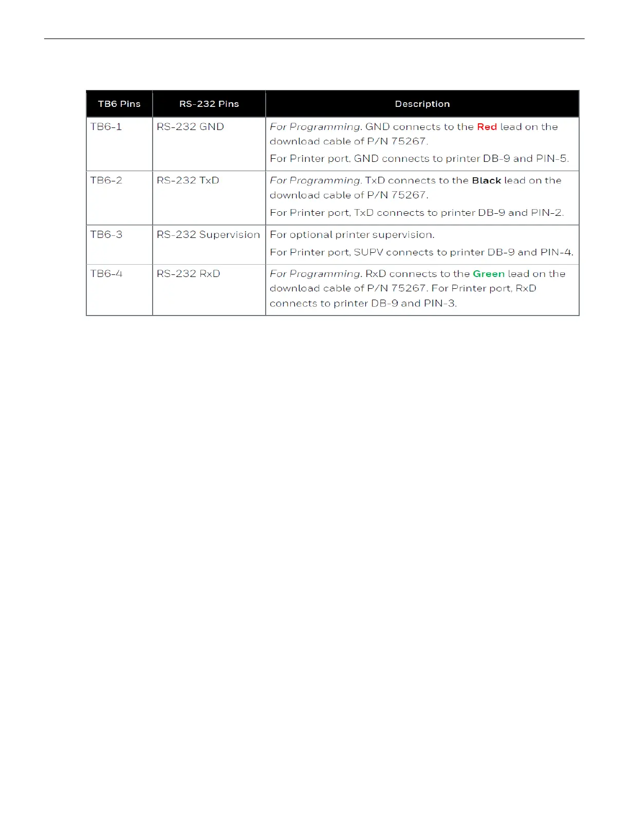
TB6 and RS-232 Connections
The pin connections are as below:
• S3 Series Panel
At the TB3 terminal of the panel,
• Connect the +ve wire to the TB3-1 pin.
• Connect the -ve wire to the TB3-2 pin.
At the TB5 terminal of the panel,
• Connect the GND wire to the TB5-1 pin.
• Connect the TxD wire to the TB5-2 pin.
• Connect the SUPV wire to the TB5-3 pin.
• Connect the RxD wire to the TB5-4 pin.
Power Connection
On the Gateway Side
Ensure that the power cable is connected with the power port of the gateway.
The power port is labeled as 7 in the Figure C.13.
On the Panel Side
• Connect the Red wire to the +ve pin in the TB2 port.
• Connect the Black wire to the -ve pin in the TB2 port.

 Loading...


