CLSS Gateway - Installation and Users’ Manual | P/N:LS10248-000HW-E | REV. F | FEB/11/2022 142
NOTIFIER® European Panels (EN) Connecting to the Panels
On the Gateway Side
1. Connect to the 24V DC external power supply or to the panel’s 24V DC power port.
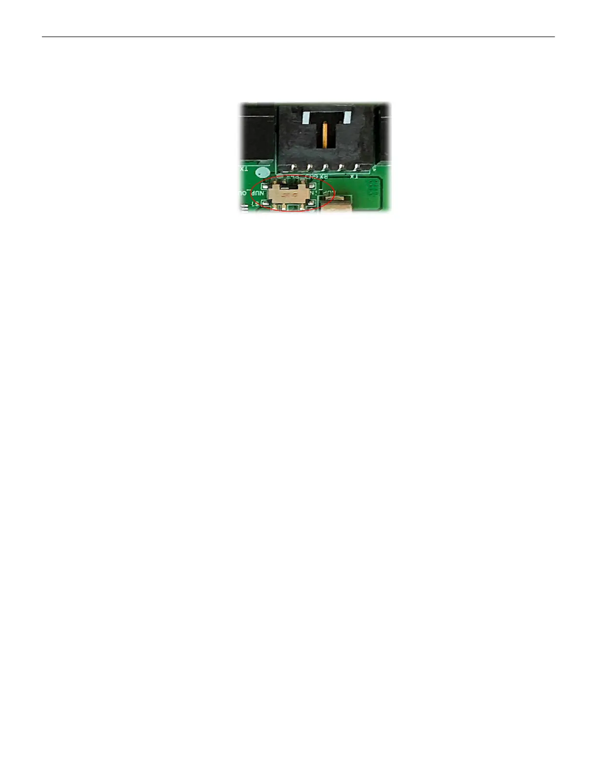
2. Ensure that the S7 switch next to the RS-232 port is switched towards NUP_OUT.
Figure C.27: The S7 Switch
On the Panel Side
• INSPIRE Panels: In the serial communication card or in the I/O card,
• Connect the Red wire to the pin 1 (Aux. DC OUT +24V).
• Connect the Black wire to the pin 2 (Aux. DC OUT GND).
External Power Supply
Use this option if the gateway is not receiving the power from the panel.
• On the Gateway Side
Connect to the power port of the gateway.
Refer to Figure C.2 where the power port on the gateway is labeled as 7. It is the P2
pin on the gateway board.
• On the External Power Supply Side
Connect to the 24V DC external power supply.

 Loading...


