Page 114 Foundation Fieldbus RMA803 Remote Indicator User's Guide Revision 4
8.7 Understanding write protection
The software write lock feature can be enabled, only if the hardware write lock feature is disabled.
If the software write lock feature is enabled without disabling the hardware write lock feature, then
the software write lock feature gets disabled automatically. If the hardware write lock feature is
selected with the hardware jumper being enabled, the selection is rejected. See Figure for jumper
location. For more information on write protection, see Table 38.
Table 38: Write lock
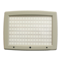
To Set the Jumper to:
Disable the Read and Write lock.
(In this mode, perform Read and Write
operation.)
“OFF” position on the Transducer board.
Enable the Write lock.
(In this mode, read operation can be performed,
but the write operation is disabled.)
“ON” position on the Transducer board.
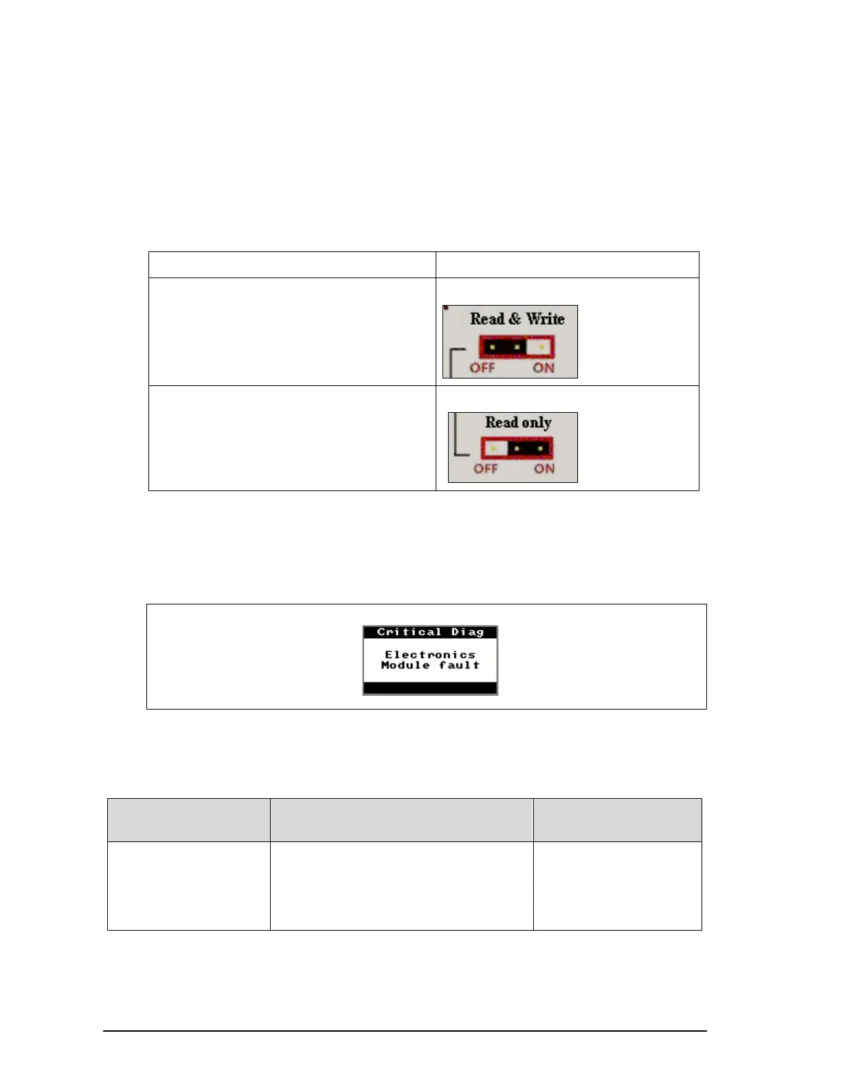
8.8 Critical Diagnostics Screens
When a Critical Diagnostic is present in the Remote Indicator, the Advanced Display will show the
screen pictured in Figure 24. This screen will be inserted into the normal screen rotation and
displayed between the user-defined operator screens. A description of the diagnostic conditions is
given Table 39, along with suggested actions for resolving the problem.
Electronics Module fault
Figure 24: Local Display Fault Diagnostic Conditions
Fault Conditions and Recommended Corrective Actions
Table 39: Fault Conditions and Recommended Corrective Actions.
Condtion Analysis
Recommended
Corrective Action
Electronics Module Fault.
A critical failure has been
detected on the FF
Electronics Module.
Use a FF communicator to read the
detailed status information from the
Remote Indicator. Refer to the appropriate
communicator manual for more information
about the possible failure causes.
Cycle power to the
Remote Indicator.
If the problem continues
to occur replace the
Electronics Module.
 Loading...