Page 6 Foundation Fieldbus RMA803 Remote Indicator User's Guide Revision 4
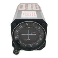
1.5 RMA803 Remote Indicator Nameplate
The Remote Indicator nameplate mounted on the bottom of the electronics housing (see Figure 1)
lists its model number, physical configuration, electronics options, accessories, certifications, and
manufacturing specialties.
Figure 3 –Typical RMA803 Nameplate
You can readily identify the series and basic Remote Indicator type from the last digit in the key
number. The last digit represents the Foundation Fieldbus.
• 3 = Foundation Fieldbus
For a complete selection breakdown, refer to the appropriate Specification and Model Selection
Guide provided as a separate document.
1.6 Safety Certification Information
An “approvals” nameplate is located on the bottom of the Electronics Assembly; see Figure 1 for
exact location. The approvals nameplate contains information and service marks that disclose the
Remote Indicator compliance information. Refer to Appendix A of this document for safety
certification requirements and details.
1.7 Display Options
The RMA803 Foundation Fieldbus Remote Indicator has Advanced Display option.
Table 2: Available Display Characteristics
Advanced Display
• 360° rotation in 90° increments
• Three (3) configurable screen formats with
configurable rotation interval
o Large process variable (PV)
o PV with bar graph
o PV with trend (1-24 hours, configurable)
• Eight (8) screens with 3-30 seconds rotation timing
• Standard and custom engineering units
• Diagnostic alerts and diagnostic messaging
• Multiple language support:
o EN, FR, GE, SP, RU, IT & TK
o EN, CH (Kanji), JP
• Square root output indication
• Supports 3-button configuration
• Supports messaging and maintenance mode
indications of the Remote Indicator
1.8 Optional 3-Button Assembly
The optional 3-Button Assembly provides the following features and capabilities:
• Increment, decrement, and enter key functions.
• With the menu-driven display:
o Comprehensive on-screen menu for navigation.
o Display configuration.
 Loading...