Revision 4 Foundation Fieldbus RMA803 Remote Indicator User's Guide Page 83
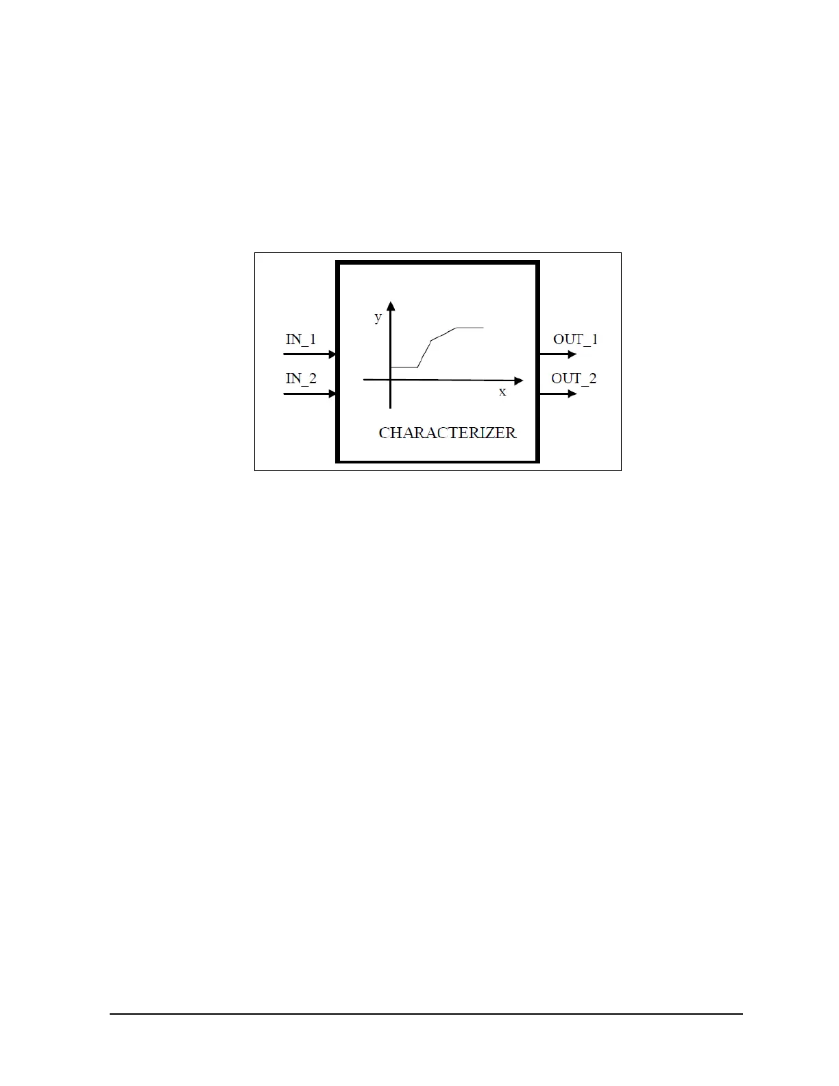
5.10 Signal Characterizer block
The Signal Characterizer block describes the input/output relationship for any type of function. The
block has two paths, each with an output that is a non-linear function of the corresponding input. The
non-linear function is configured based on a single look-up table with 21 arbitrary x-y pairs. To use
the block in a control or process signal path, the status of an input is provided to the corresponding
output. To use the backward control path, the block provides an option to swap the axes of the
function.
Figure 18: Signal Characterizer Block
The block calculates OUT_1 from IN_1 and OUT_2 from IN_2 using a curve given by the co-
ordinates:
[x1; y1], [x2; y2] ... [x21; y21]
Where,
• x is the Input, and
• y is the Output.
The x-coordinates are given in engineering units of X_RANGE. The y-coordinates are given in
engineering units of Y_RANGE.
Execution
Figure describes the components of the block. The output value is calculated by linear interpolation
between two points enclosing the input value. OUT_1 is associated to IN_1 and OUT_2 to IN_2 by
the same curve, but there is no association between IN_1 and IN_2 or between OUT_1 and OUT_2.
 Loading...