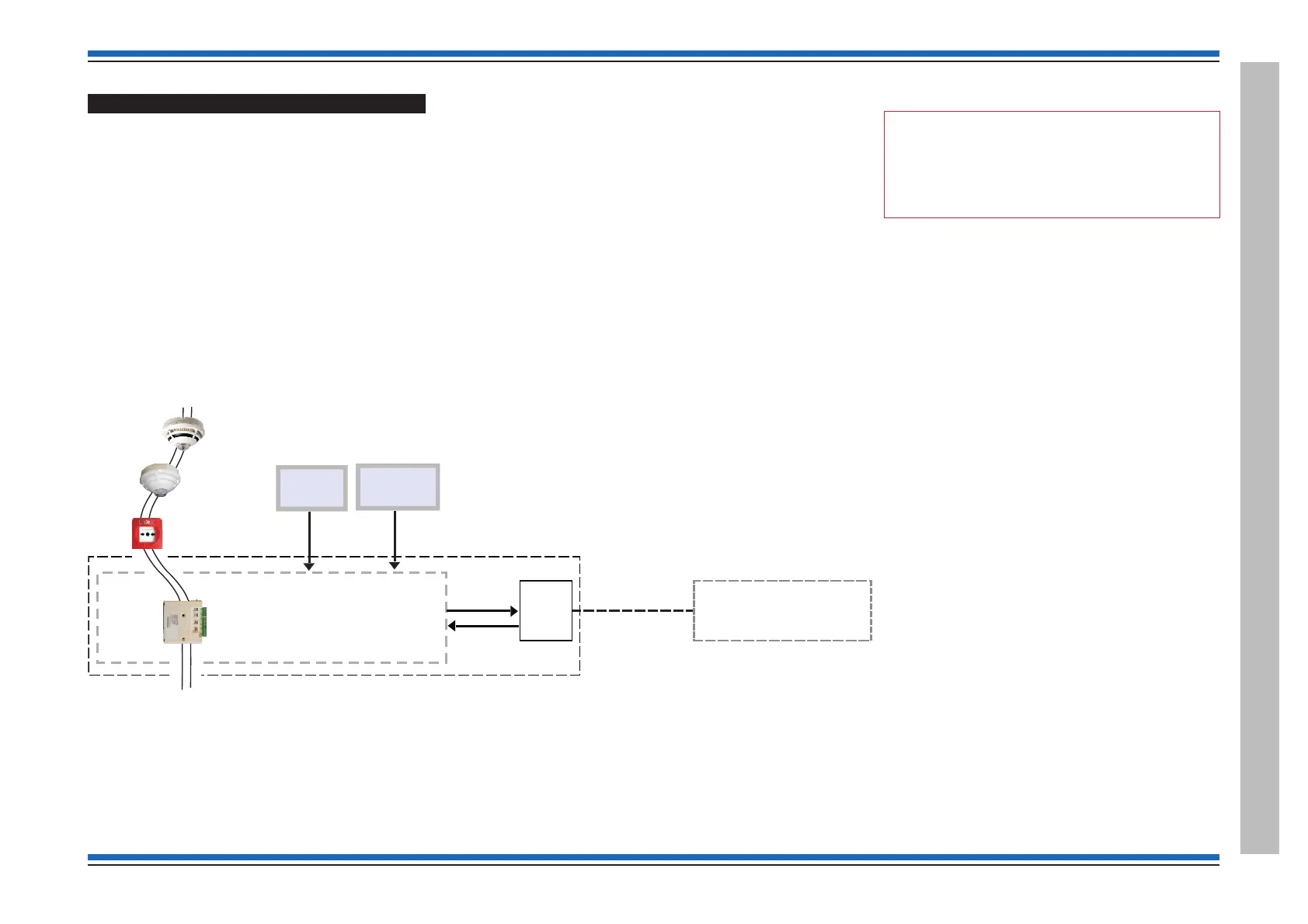
Fire Alarm Routing Equipment (FARE)
¨
There can be one FARE Interface per Vigilon System.
FARE Interface can be a LV Interface unit S4-34420, but can also be a S4-34450.
Other interface units can be configured FARE, these include S4-34440-02, S4-34440-12, S4-34401 and S4-34404.
¨
a FARE Interface device is automatically placed in plant Sector 32 (as default) and is unaffected by operation of SOUND
ALARMS control
¨
a FARE Interface device may be switched ON or OFF from the panel menus select:
Menu On/Off button to select [Control] -> <etc> -> [FARE] -> [ON] or [Off] -> [E]
¨
a FARE device may be Enabled or Disabled from the panel menus, select:
Menu On/Off button to select: [Control] -> [Enable] / [Disable] -> <etc> -> <etc> -> <etc> -[FARE] -> [E]
"
Where a FARE interface is required to be
disabled then use the FARE device disablement
option.
4188-856_issue 7_07/15_Generic Vigilon (Compact + VA) Comms. 155
Vigilon 4/6 loops & Compact (VA) panels & network nodes
Appendix C - Guidelines for standalone system commands
SWITCH
ON / OFF
H
MCP
LV INTERFACE #
ONE LV INTERFACE #
DEVICE IN A VIGILON SYSTEM
CAN BE SET UP TO OPERATE AS
FIRE ALARM ROUTING
EQUIPMENT (FARE)
Sensor
Alarm
device
ALARM RECEIVING CENTRE
FARE
ENABLED OR
DISABLED
ACTION
SETUP
as FARE
Confirmation
Vigilon loop
# - LV Interface unit (S4-34420)
 Loading...