Commissioning instructions
48 4188-856_issue 7_07/15_Generic Vigilon (Compact + VA) Comms.
Vigilon Compact Voice Alarm Panel - (legacy product)
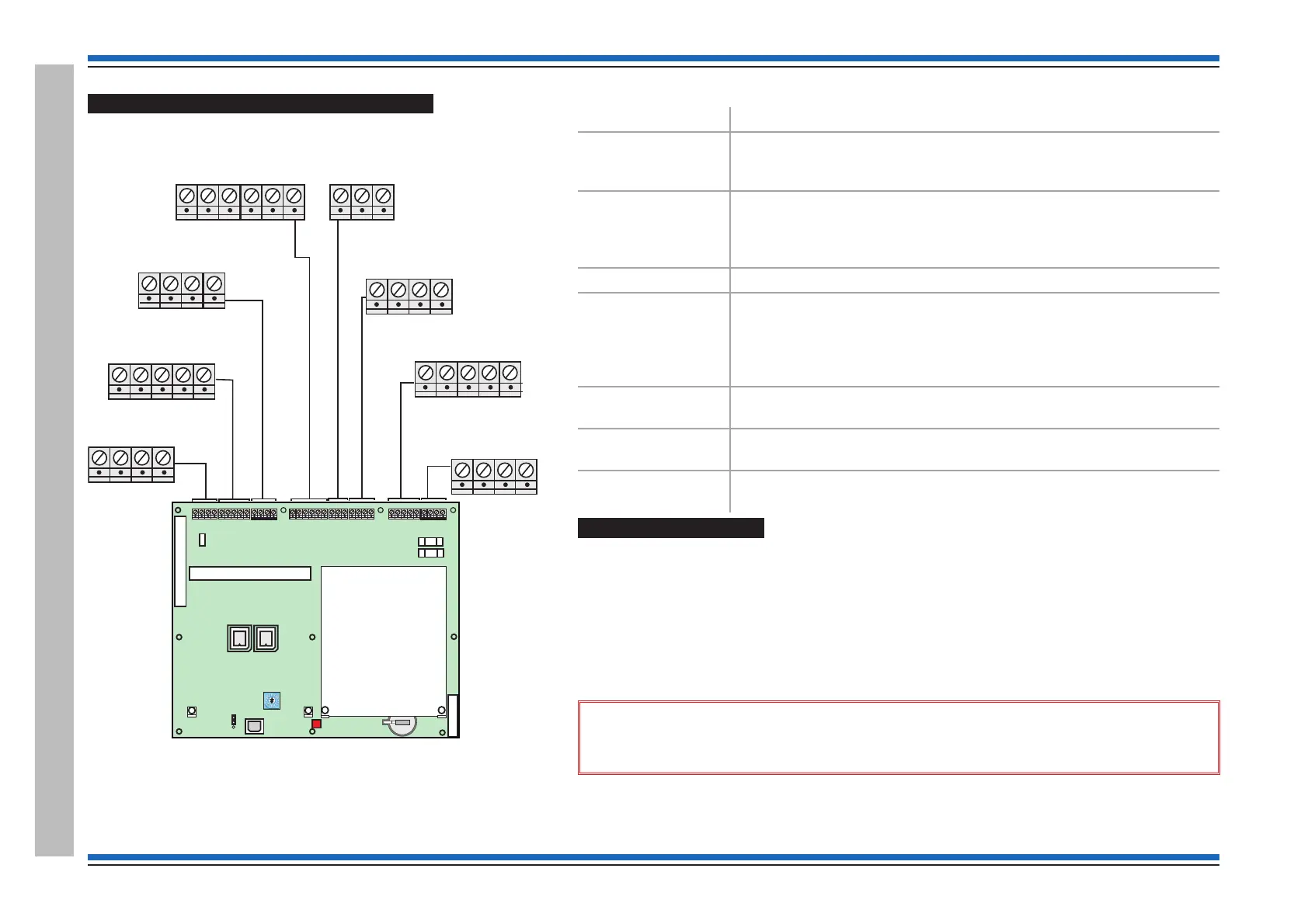
Terminals on the Master Control Board
Descriptions of MCB terminals
Terminals Description
24V, 0V, B and A These terminals accept the connection of a repeat indicator panel
(Port 0). The power terminals may be used on a Network node to
supply BACnet Gateway card.
NC, C and NO
Aux 1 - 2-sets
Aux 2 - 1-set
These are auxiliary relay contacts. The auxiliary relay 1 is factory set
as a normally de-energised relay that operates with any fire event.
The auxiliary relay 2 is factory set as a normally energised relay that
operates (de-energises) with any fault event.
0V, TX, A, RX & B These are terminals for RS232 or RS485 (Ports 1 or 2 respectively).
L1, 0V, L2, 0V
(Loop 1 and Loop 2)
These terminals accept the connection of system devices on a loop
circuit that starts at L1 and ends at L2. Devices that can be connected
on the loop circuit include addressable fire sensor/sounders, manual
call points, interface units repeat/mimic panels and micro and mains
distributed amplifier units
MA1+, MA1-, MA2+
and MA2-
These terminals can accept two master alarm circuits that can operate
24V conventional alarm devices.
0V and MIP These are monitored input terminals that can accept the connection of
a switch. An active input will trigger Command build 250.
NC, C and NO
(clean contact)
These are voltage free relay contact outputs that operate with a fire
event.
Pre power up checks
Ensure the following external circuit cables are left disconnected at this stage of commissioning:
•
loop circuits
•
audio circuits
•
clean contacts
•
auxiliary circuits
•
master alarms (the 10K Ohm end-of-line resistor is fitted to inhibit a fault indication).
•
monitored input (the 10K Ohm end-of-line resistor is fitted to inhibit fault indication).
&
Ensure the mains cable to the panel is securely connected to the mains terminal
block on the Power supply unit (PSU).
¨
Ensure all cards are securely fitted into their appropriate slots on the MCB.
¨
Ensure all ribbon cables are securely fitted into their respective sockets.
BATT1
PB15
REPEAT
INDICATOR
RS-485
24V
BA
0V
PB15 PB6
PB9
P2 CARD 1
IC3
KEYBOARD
IC16
POWER
SUPPLY
P12
MA2 - FS2 250mA
MA1 - FS1 250mA
P1 CARD 2
P16
P13
SW1
RESET
24V B A
0V
TX1 RX1
0V
PB8
MA1+
MA1- MA2+
MA2-
0V
MIPNC C
NO
FIRMWARE
BACKUP
Loop Card
Master Control Board
PB10
PB7
L1 0V L2 0V
24V
FS3 200mA
TX2 RX2
PB14
L1 0V L2 0V
NC
C
NO
NC
C
NO
NC
C
NO
PB11
PB8
MASTER ALARMS
MA1+
MA1- MA2+
MA2-
PB9
MONITORED INPUT
and CLEAN CONTACTS
0V
MIP
NC C NO
PB10
AUXILIARY RELAY 1
PB7
LOOP 1
L1
0V
L2
0V
PB14
LOOP 2
L1 0V L2 0V
NC
C
NO
NC
C
NO
NC
C
NO
PB11
AUXILIARY RELAY 2
PB6
RS-232
TX1 RX1
0V
TX2 RX2
 Loading...