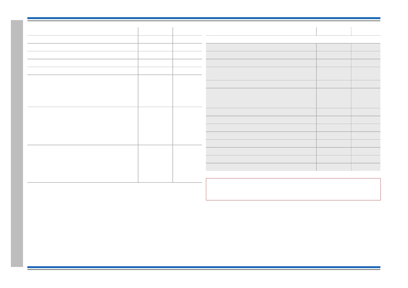
Device digitalI/O channels
MCP . . . O 6
Repeat panel . . . O -
Zonal mimic . . . O -
Mimic panel . . . O -
T-breaker . . . O
Loop interface all possible
I - input
O - output
1-channel 1
2-channel 2
3-channel 3
4-channel 4
5
Interface unit (mains powered) all possible
I - input
O - output
1-channel 1
2-channel 2
3-channel 3
4-channel 4
5-battery
6-mains
S cubed OOOO
1 - IR control
2 - Tone
3 - Power
4 - VAD
(Strobe)
5
Device digitalI/O channels
The legacy products below are for reference
S-Quad Dual Optical Heat Sensor Strobe O..O 1,2,4,5
S-Quad Dual Optical Heat Sensor Sounder . OOO 1, 2, 4, 5
S-Quad Dual Optical Heat Sensor Speech Strobe OOOO 1, 2, 4, 5
S-Quad Dual Optical Heat Sensor CO Speech
Strobe
OOOO 1, 2, 3, 4, 5
Slave LED . . . O +L
Sounder . OO .
3 - Low freq.
2 - On/Off
Repeat sounder . OO .
Optical . . . O 1
Optical heat . . . O 1,2
Heat . . . O 4
Slave Relay O . . O+R
Single channel interface unit IO.O 1,2,5
Loop powered zone module I . . O 1,5
Optical/Heat Sounder . OOO 1,2
"
The correct device type may not be displayed if the loop circuit has allocation faults.
¨
Check that the device is of the correct type and is suitable for the area in which it is
installed.
¨
Check the digital status of all devices.
¨
On successful allocation check that the total number of devices found equals the
number installed. Also note there will be a loop voltage on the unconnected end of the
cable.
Commissioning instructions
66 4188-856_issue 7_07/15_Generic Vigilon (Compact + VA) Comms.
Checking device STATUS
 Loading...