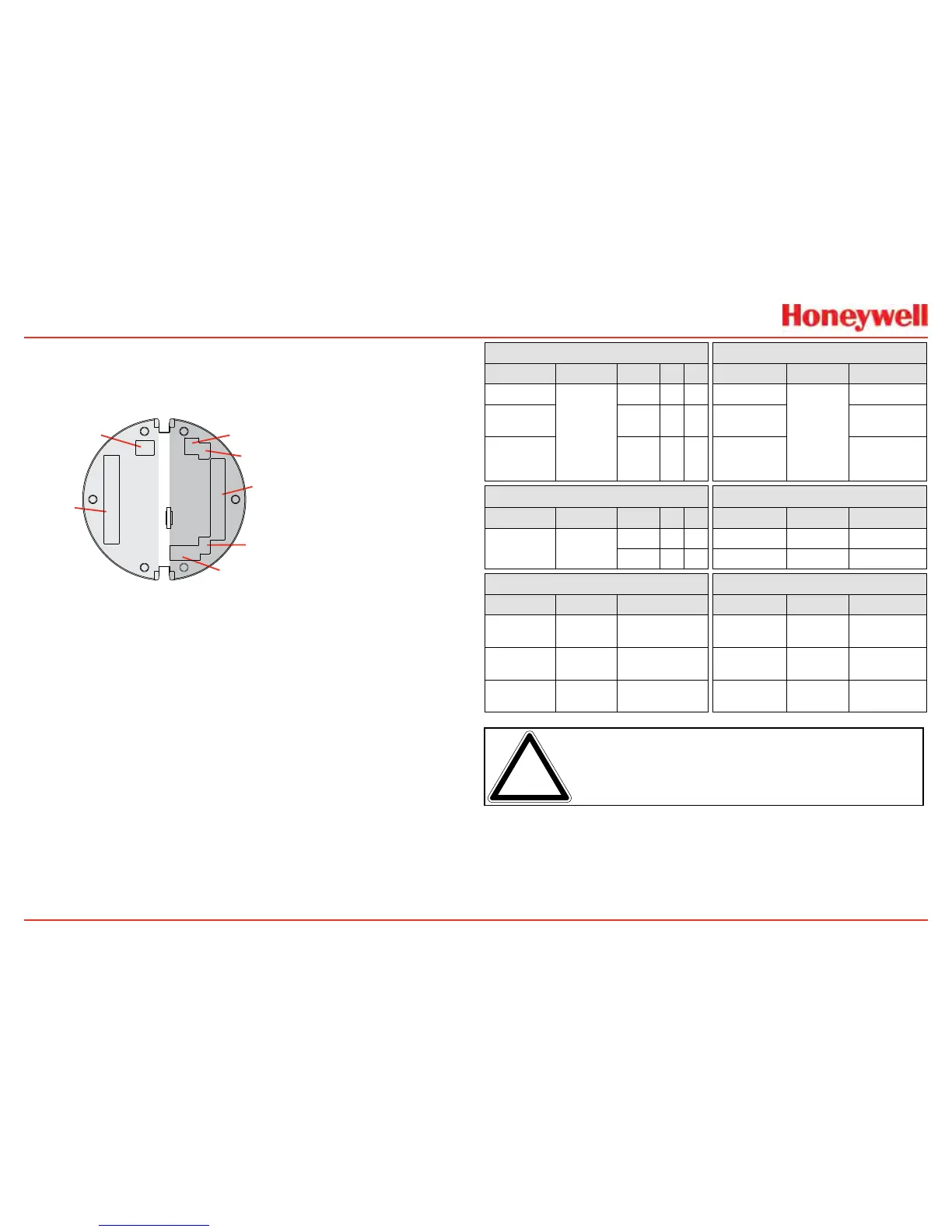
Figure 35. XNX Personality Board Terminal Block Legend
Eachofthepersonalitiesuseasingleterminalblockfor
connectionwiththeexceptionoftheIRpersonality,which
requiresasecondterminalblock�
Thepersonalityboardsalsoprovideadedicatedpairofjumper
switchestodeneoutputofthetransmitterasisolated4-20mA,
Sink20mA,orSource20mAaswellasaservicejumpertoallow
powertothelooptocontinuewhenthetransmitterisbeing
serviced�AseparateconnectorisusedtoactivatelocalHART
(seeSection2�3�1)�
LocalHARTprovidesanexternalaccesstocontrolthe
transmitter�Anintrinsicallysafe(IS)barrierinsidethetransmitter
allowstheusertoattachanexternalhand-heldinterrogator
forprogrammingandconguration�Theexternalinterfaceis
intrinsicallysafe�Itisinstalledinthetransmitter’slowerleft
cable/conduitport�
Table A Table B
Board Type Function S1 S2 Board Type Connection Function
ECPersonality
4-20mA
Output
Source
ECPersonality
TB1
Power,4-20mA
mV
Personality
Sink
mVPersonality
Power,4-20mA,
Sensor
IR
Personality
Isolated
IRPersonality
Power,4-20mA,
IRPowerand
Signal
Table C Table D
Board Type Function S3 S4 Board Type Connection Function
IR
Personality
IR4-20mA
Input
Source
ECPersonality J2 ECISBarrier
Sink
IRPersonality TB2 ComAandB
Table E Table F
Board Type Connection Function Board Type Connection Function
Relay TB4
RemoteReset
Connector
Relay TB3 RelayOutput
Modbus SW5
BusLoop
Terminators
Modbus TB3 DataConnection
Foundatin
Fieldbus
SW5 SimulationMode
Foundation
Fieldbus
TB3 Dataconnection
Note:OpenloopfaultsarenotavailableduetoHART,Modbus,and
FoundationFieldbusinterfaceswherea4-20signalcannotbeused.
Inthiscase,openloop,0mAmustbeusedasthediagnostic.
TheOptioncircuitboardsvarydependingupontheoption
selectedwhenordered�Onlyoneofthethreeavailableinterface
options(relays,Modbus,orFoundationFieldbus)canbe
attachedtotheXNXtransmitter�Wheninstalled,connectionsto
theoptionsaremadetoconnectorsatthebottomofthePOD�
 Loading...


