81
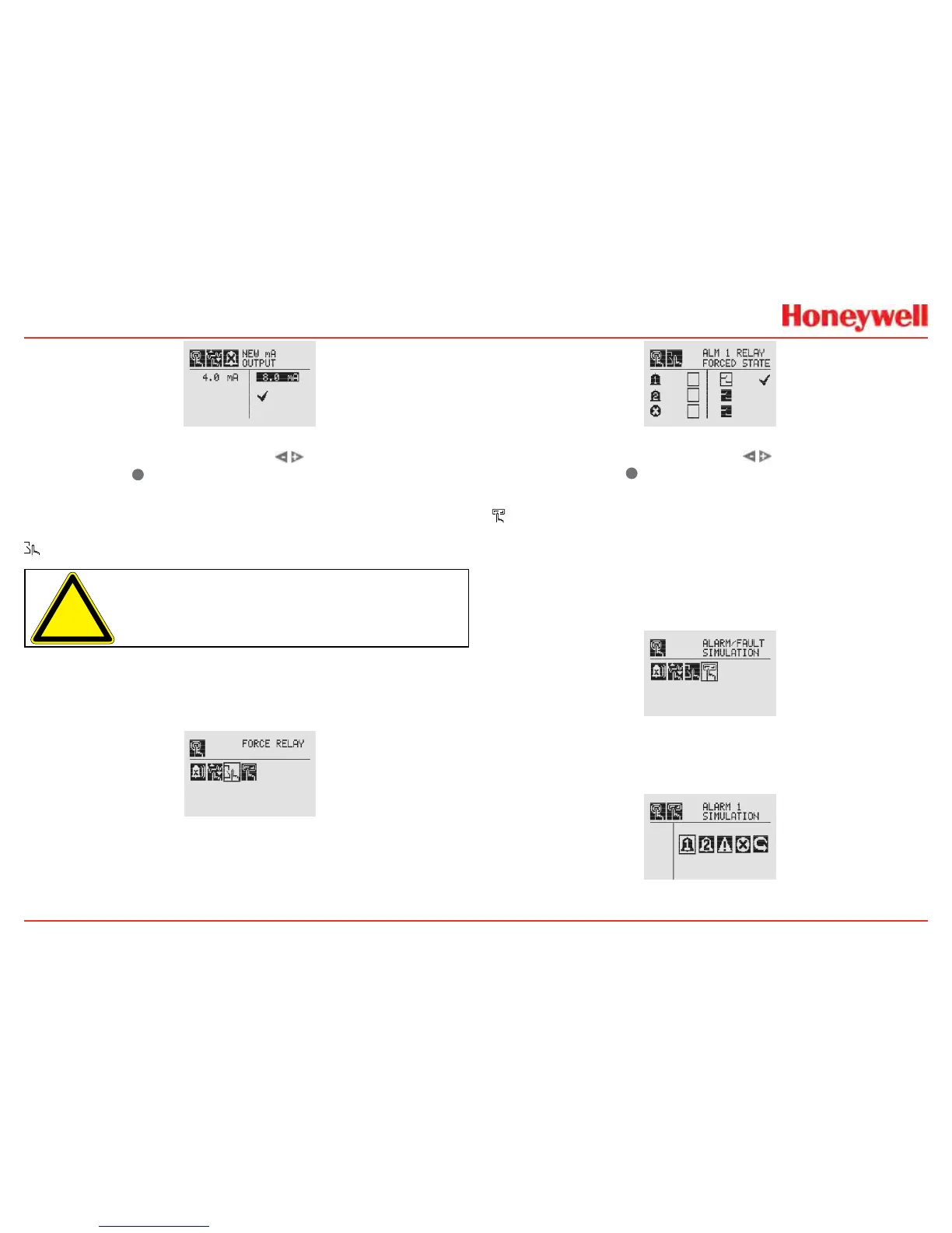
Figure 153. New mA Output Screen
Oncethenewvalueisinput,usethe switchestomovetothe
‘ü’andusethe
✓
magneticswitchonthefrontpaneltosetthe
mAoutput�
Force Relays
Caution: Anyrelayconditionssetinthismenuwillreverttothe
normaloperatingvalueswhenexitingtheTestMenu.Formore
informationonsettingtherelayoptionsfornormaloperation,see
RelayOptions.
TheForceRelaymenuallowsperipheraldevicesdrivenbyrelays
fromthetransmittertobetested�Dependingontherelayoptionsset
intheRelayOptionsmenu(seeRelayOptions),therelaywillbeopen
orclosed�
Figure 154. Force Relays Screen
TheRelayStatescreenshowsthecurrentrelaycongurationin
theleftcolumn�Theoutputcanbecontrolledbychangingthe
valueinthecolumnontheright�
Figure 155. Relay State Screen
Oncethenewvalueisinput,usethe switchestomoveto
the‘ü’andusethe
✓
magneticswitchonthefrontpanelto
changetheconditionoftherelay�
Alarm/Fault Simulation
AlarmandFaultsimulationworkintandemwiththeprevious
sections(ForcemAOutputandForceRelays)toallowthorough
testingoftheXNXtransmitterandtheperipheralwarningand
safetydevicesattached�Figure156showsthemenuchoices
forselectinganalarmorfaultsimulation�
Figure 156. Alarm/Fault Simulation Screen
Selectinganalarmleveltosimulateactivatesaconrmation
screen�
Figure 157. Alarm/Fault Simulation Menu
 Loading...


