38
LabelsappliedtothebackofthePODidentifyeachofthe
connectionpoints�
Note: Pins2and4ofterminalblockTB1havenointernalconnection
onthepersonalityboard.Whenusedwiththeterminalblockjumpers,
pins2and4canprovideadditional4-20mAconnectionsorsupply
powerfordaisy-chainedunits.
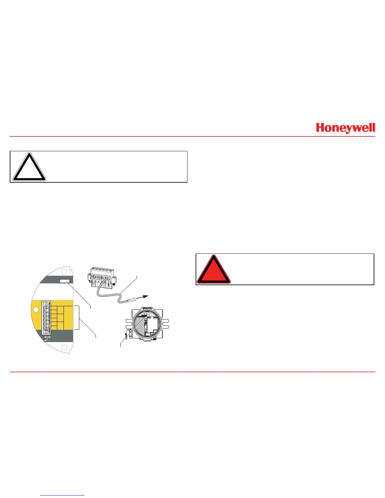
2.2.5
Foundation Fieldbus Wiring
FoundationFieldbusconnectionstotheXNXtransmitterare
madethroughapluggableterminalblockontheFoundation
Fieldbusoptionboard,showninFigure39�Asimulationswitch
(SW5)isincludedontheboardtoenable/disablesimulation
mode�Terminals3-1through3-4areprovidedtofacilitatebus
wiring;thereisnointernalconnectiontootherXNXcircuitry�
Terminal3-1isconnectedinternallyto3-2�Similarly,terminal3-3
isconnectedinternallyto3-4�
+
+
TB-3 Modbus
Use shorting jumper
supplied to maintain
connection during
service
S5 Sim Mode
Out
In
3-1
3-2
3-3
3-4
3-5
3-6
F+
F+
F-
F-
FS
FS
TB-3 FFB
Jumper
assignments
1
2
3
4
5
6
to internal
ground lug
SW5 -
Sim switch
Internal ground lug
Foundation Fieldbus
ground cable
Figure 39. XNX Foundation Fieldbus option board and terminal block
2.2.6 Terminal Block Connections
Connectionstothetransmitteraremadeviapluggableterminal
blockssecuredtothebackofthePOD�Theterminalblocksare
keyedandpolarized�Acolorcodedlabelassistsinwiringwhen
theblockisremovedfromthePOD�
Theterminalsaresuitableforusewith12to28AWGor0�8to
2�5mm
2
wire�Wireinsulationmustbestripped5/16”(0�312”)or
8mm�Tighteneachterminaltoamaximumof4�5in-lbs(0�51Nm)�
Uptofourterminalblocksareprovided;eachhaving2,6,9,or10
positions(seethe
XNXQuickStartGuide
foradditionaldetails)�
Twoterminalblockjumpersareincludedtoprovideanelectrical
connectionwithoutconnectiontothePersonalityBoard�Install
thejumpersbetweenpins1and2andbetweenpins3and4to
supportmulti-nodewiring�
Warning:WhenthetransmitterisequippedwiththeoptionalRemoteMount
Kit,theremotesensormustbesecurelymountedinafixedposition.TheRemote
Sensorkitisnotintedndedtobeusedasahand-heldsensor.
 Loading...


