53
2.3.2 Relays
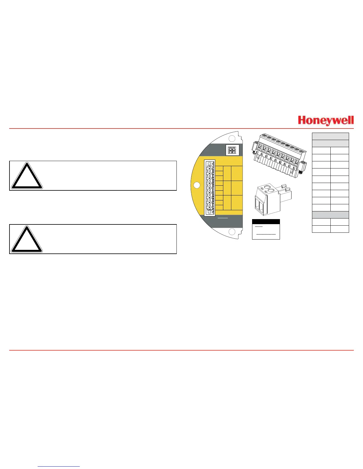
Therelayoption(XNX-Relay)provides3form“C”SPCOcontacts
foralarmandfaultindication�TB4allowsalarmstobereset
remotely�
Note: ThisoptionisnotavailablewhentheModbusorFoundation
Fieldbusoptionsareinstalled.
Wiringfortherelaysisthroughanavailablecable/conduitportto
apluggableterminalblock�SeeFigure35fortheterminalblock
legend�
Note: Asecond,black-handledscrewdriverisincludedforuseon
terminalblocks2and4.Thistoolissmallerthanthemagneticwand
andisdesignedtofitintotheterminalconnectionsonTB4.
TheXNXtransmitterhasthreerelays:relay1isforalarmlevel
1,relay2isforalarmlevel2,andrelay3isforfaultsandspecial
states�Allspecialstatesareindicatedbythefaultrelay�
HoneywellAnalyticsrecommendsthatthefaultrelaybeusedinall
installationstomaintainsafeoperation�SeeSetAlarmValuesfor
moreinformation�
Therelaystateisrefreshedevery2seconds�Thefaultrelayis
normallyenergizedindicatingproperoperation�Intheeventof
powerfailureorfault,theC-NOconnectionwillopen�
Warning: Power
externally supplied.
Disconnect at source
prior to servicing.
3-5
3-4
3-3
3-2
3-1
3-6
3-7
3-8
3-9
C
NC
TB4
Remote
Reset SW
Relay Ratings
250VAC 5A
24VDC 5A
NO
C
NC
NO
NC
C
NO
Fault Level 2 Level 1
TB-3 RELAY
TB3 Relay Connections
Warning: Power externally
supplied, disconnect at source
prior to servicing
Relay Contact Ratings:
250 VAC 5 amps
24 VDC 5 amps
Relay
TB3
1
NC
2
C
3
NO
4
NC
5
C
6
NO
7
NC
8
C
9
NO
TB4
1
1
2
2
1
2
3
4
5
6
7
8
9
TB3
1
2
TB4
Figure 59. XNX Relay Option Board Terminal Blocks
2.3.3 Modbus
TheoptionalModbusinterfaceallowsalltransmitterlocal
userinterface(LUI)functionsandparametersettingstobe
transmitted�
Modbusisamaster-slavesprotocol�Onlyonemaster(ata
time)isconnectedtothebus�Upto247slavenodesarealso
connectedtothesameserialbus�Modbuscommunicationis
alwaysinitiatedbythemaster�Theslavenodesnevertransmit
datawithoutreceivingarequestfromthemasternode�Theslave
nodesnevercommunicatewitheachother�Themasternode
initiatesonlyoneModbustransactionatatime�

 Loading...


