54
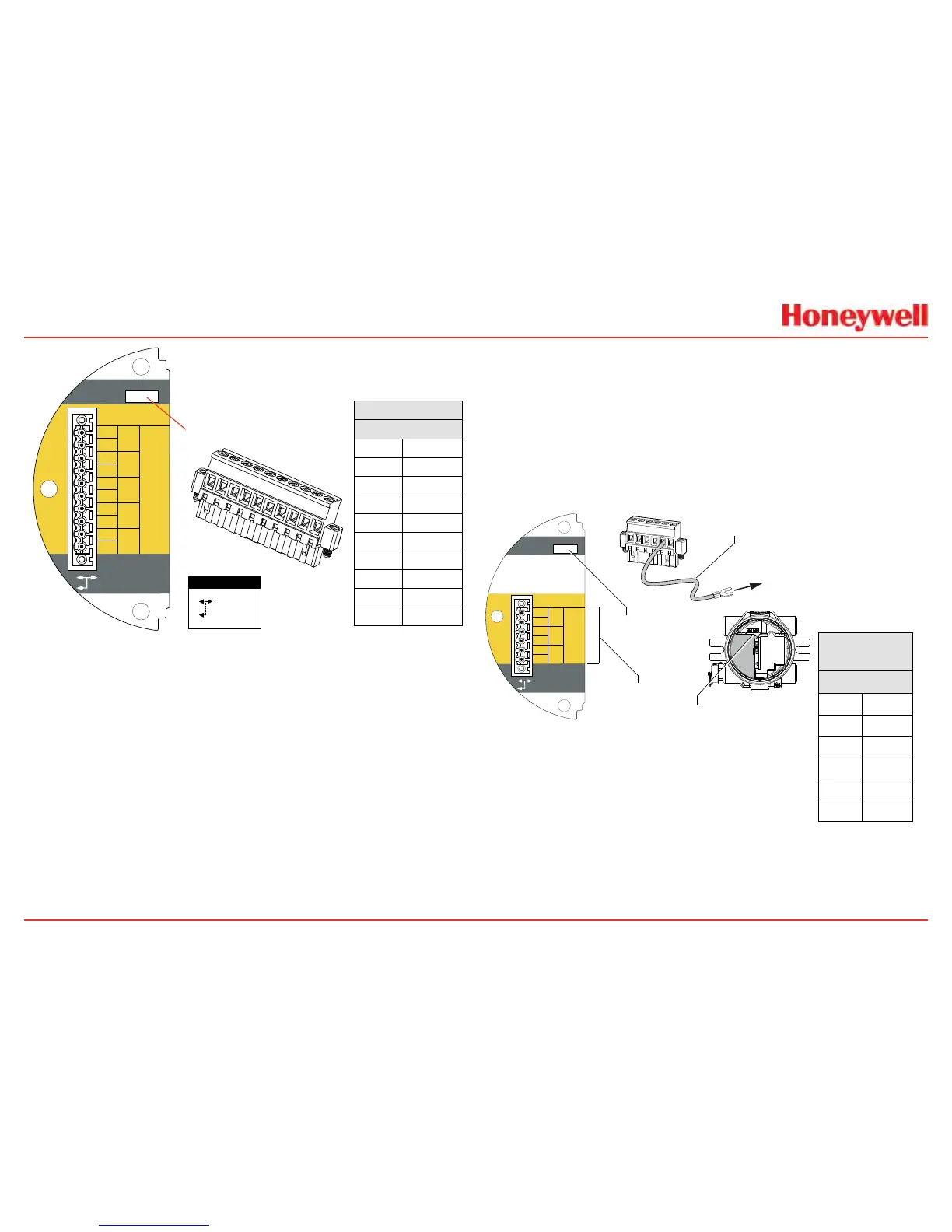
Terminals3-1through3-4areprovidedtofacilitate
buswiring;thereisnointernalconnectiontootherXNX
circuitry.Terminal3-1isconnectedinternallyto3-2.
Similarly,terminal3-3isconnectedto3-4
3-5
3-4
3-3
3-2
3-1
3-6
3-7
3-8
3-9
3-10
A
-
-
+
+
A
B
B
S
TB-3 Modbus
S
Use shorting jumper
supplied to maintain
connection during
service
S5 EOL Term
Out
In
R
T
=120
TB3 Modbus Connections
Use Jumper
to maintain
connection
during service
SW5 - Loop Termination
Modbus
TB3
1
+
2
+
3
-
4
-
5
A
6
A
7
B
8
B
9
S
10
S
1
2
3
4
5
6
7
8
9
10
Figure 60. XNX Modbus Option Board Terminal Block / Jumper Switch
ModbusconnectionstotheXNXaremadethroughapluggable
terminalblockontheModbusinterfacecircuitboard�Modbus
RTUprotocolusesASCII/Hexprotocolsforcommunication�See
Figure35fortheterminalblocklegend�Aloopterminationpoint
(SW5)isincludedontheModbusinterfaceboardtoprovide
terminationoftheModbusloop�
2.3.4 Foundation Fieldbus
FoundationFieldbusconnectionstotheXNXtransmitterare
madethroughapluggableterminalblockontheFoundation
Fieldbusoptionboard,showninFigure60�Asimulationswitch
(SW5)isincludedontheboardtoenable/disablesimulation
mode�Terminals3-1through3-4areprovidedtofacilitatebus
wiring;thereisnointernalconnectiontootherXNXcircuitry�
Terminal3-1isconnectedinternallyto3-2�Similarly,terminal3-3
isconnectedinternallyto3-4�
+
+
TB-3 Modbus
Use shorting jumper
supplied to maintain
connection during
service
S5 Sim Mode
Out
In
3-1
3-2
3-3
3-4
3-5
3-6
F+
F+
F-
F-
FS
FS
TB-3 FFB
Jumper
assignments
1
2
3
4
5
6
to internal
ground lug
SW5 -
Sim switch
Internal ground lug
Foundation Fieldbus
ground cable
Foundation
Fieldbus
TB3
1
F+
2
F+
3
F-
4
F-
5
FS
6
FS
Figure 61. Foundation Fieldbus Option Board, Terminal Block, Jumper Switch
 Loading...


