EasyManuals Logo

Honeywell XNX Technical Manual

Honeywell XNX
200 pages
To Next Page IconTo Next Page
To Previous Page IconTo Previous Page
Page #76 background imageLoading...
Page #76 background image
XNX Universal Transmitter
Section 2 - Installation and Operation
74
todecrementorincrementthevalueuntilthedesiredvalue
appears�Use
toselectthevalueandmovetothenextsetting�
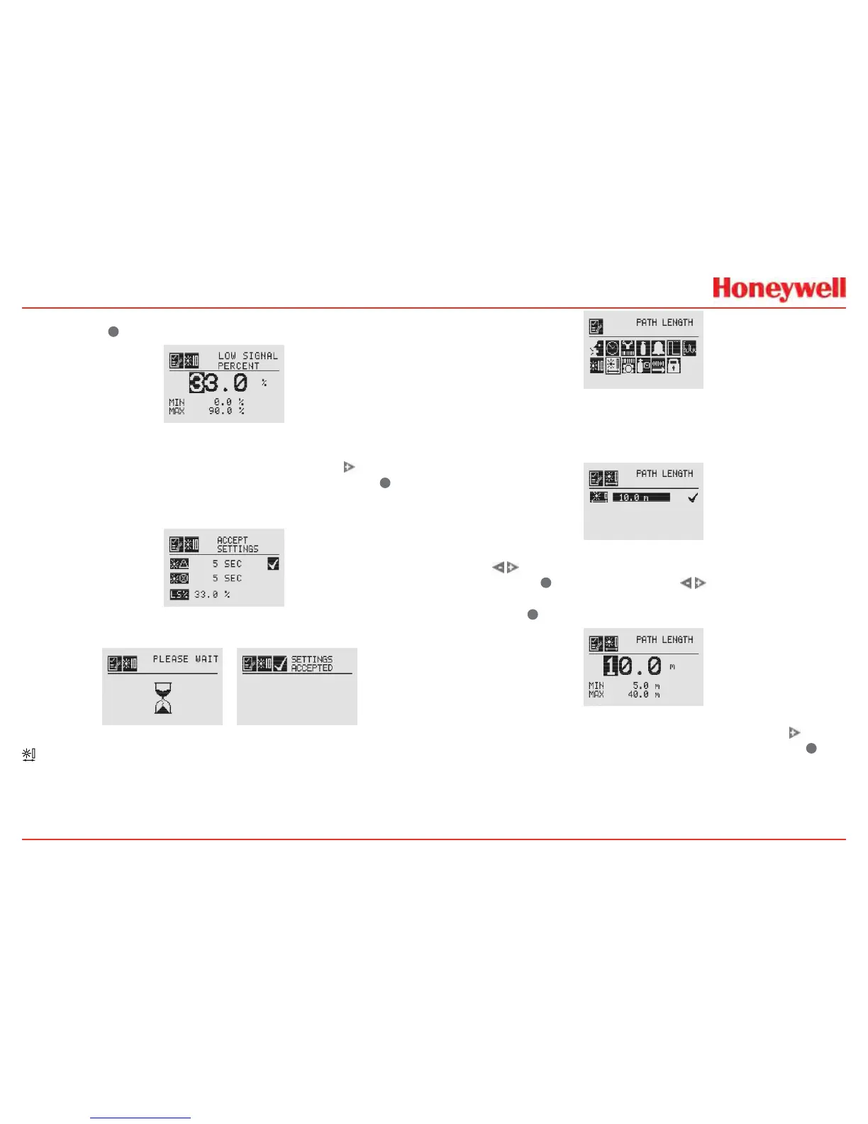
Figure 117. Setting the Low Signal Percentage
OncethevaluesforBeamBlockWarning,BeamBlockFault
andLowSignalPercentagehavebeenset,usethe
switchto
highlightthe‘ü’ontherightsideofthedisplay�Thenuse
to
acceptthechangestotheXNX�If‘ü’isnothighlighted,noneof
thechangeswillbesaved�
Figure 118. Accept Beam Block Changes
 
Figure 119. Beam Block Changes Accepted
Path Length
Thedistance(inmeters)betweenthetransmitterandthereceiver
issetthroughthePathLengthmenu�Thismenuisavailableonly
ifthetransmitterisconnectedtoaSearchlineExcelsensor
Figure 120. Path Length Menu
SettingthePathLengthordistancebetweenthetransmitterand
receiveroftheExcelletsthedevicesdeterminetheoptimum
settingsforthebeamstrengthfortheapplication�
Figure 121. Current Path Length Setting
Usethe switchestomovetothedesiredPathLength
settinganduse
toselectit�Usethe switchesto
decrementorincrementthevalueuntilthedesiredvalue
appears�Use
toselectthevalueandmovetothenextsetting�
Figure 122. Setting Path Length
OncethevaluesforPathLengthhavebeenset,usethe switch
tohighlightthe‘ü’ontherightsideofthedisplay�Usethe
to
acceptthechanges�

Table of Contents

Other manuals for Honeywell XNX

Questions and Answers:

Question and Answer IconNeed help?

Do you have a question about the Honeywell XNX and is the answer not in the manual?

Honeywell XNX Specifications

General IconGeneral
Ingress ProtectionIP66/67
Product TypeUniversal Transmitter
Enclosure RatingIP66/67
DisplayLCD
Communication ProtocolsHART, Modbus, Foundation Fieldbus
Power Supply24 VDC nominal, 18-32 VDC
Operating Temperature-40°C to +65°C (-40°F to +149°F)
MaterialAluminum or Stainless Steel
Gas TypesToxic, Oxygen, and Combustible gases
Output4-20 mA
Relays3 programmable relays
ApprovalsATEX, IECEx, UL, CSA
Sensor CompatibilityElectrochemical, catalytic, infrared, and other sensor types

Related product manuals