45
mV Remote Sensor Mounting
Thesensorcanbemountedremotelyfromthetransmitter;the
installationwillvarybyinstalledlocation,sensorandthreadtype
used�Toremotelymountthesensor,followthisprocedure:
1�Unscrewthetransmitter’sweatherproofcoverandloosen
theretainerlockingscrewwiththesuppliedhexkey�
2�Runconduitfromoneofthetransmitter’savailableconduit
portstothelocationoftheremoteterminalhousing�
Aterminalhousingprovidesamountingbaseforthe
sensor�Theinstallationwiringenterstheterminalhousing
viaconduit�
UL/CSA Aluminum Junction Box
2441-0022
UL/CSA Stainless Steel Junction Box
2110B2103
ATEX/IEC Junction Box
00780-A-0100
Figure 47. Remote Terminal Housings
ThedistancebetweentheXNXTransmitterandremote
installationmustcomplywiththeseparameterstoinsureproper
operation�Distancesaredependentonsensortypesandthe
wiregaugeused�
AWG Metric Wire Gauge
MPD CB1, 705 Series.
Sensepoint Series
Sensors
MPD IC1, IV1 & IF1 Sensors
24 0.25mm
2
12m(47ft.) 30m(97ft.)
22 20m(65ft.) 50m(162ft.)
20 0.5mm
2
30m(97ft.) 80m(260ft.)
18 50m(162ft.) 120m(390ft.)*
16 1.0mm
2
80m(260ft.)* 200m(650ft.)*
* FrequencyofZerocalibrationmayincreaseduetothechangesinwireresistancefromchangingtemperature.
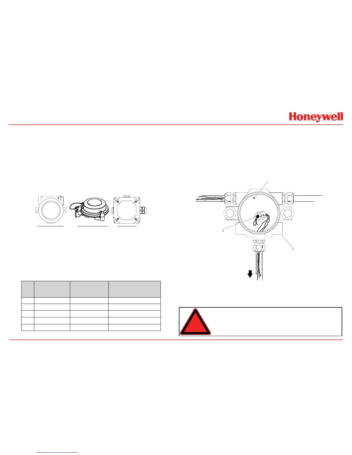
3�WirethepluggableterminalblockasshowninFigure
45thenplugtheconnectorintothebackofthemV
personalityboard�InremotemountMPDcongurations,
the3wiresconnectingthepluggableterminalblockand
theremoteMPDmustberoutedthroughthesupplied
ferritebead(HoneywellAnalyticspartno�0060-1051,
suppliedintheaccessorykit)asshowninFigure48�
Internal Ground Lug
(do not use)
Power
Ferrite Bead
for Remote
Sensor Wiring
mV
Remote
Sensor
XNX Universal Transmitter
Figure 48. Ferrite bead wiring
4�Mounttheremotesensorjunctionboxwithsufcientroom
belowtotthesensorandweatherproofcover�
Warning: Installthejunctionboxaccordingtolocalcodesand
manufacturer’srequirements.
 Loading...


